
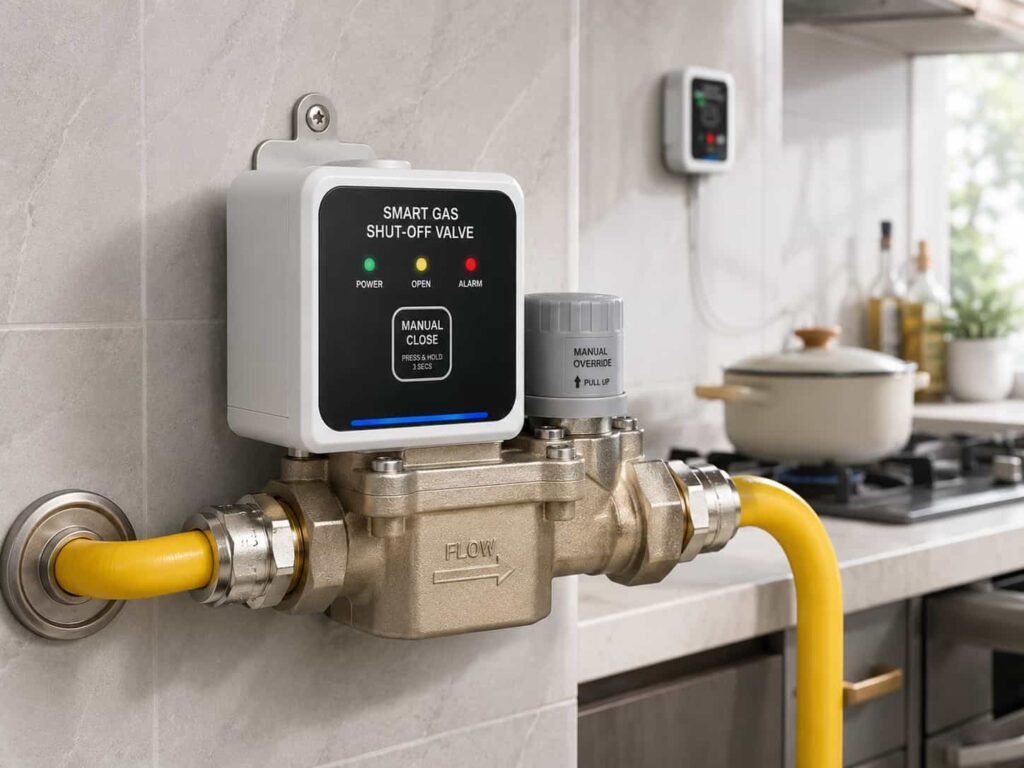
Every kitchen has one now, and almost nobody looks at it twice. A fist-sized valve bolted to the gas pipe just before the stove hose. For most of the last decade it was a purely mechanical part with no electronics inside. Then, market by market, residential gas-safety codes began requiring an automatic shut-off. Once manufacturers started putting microprocessors inside the valve body, the pressure sensor stopped being an optional extra. It became the sensing core of the whole device.
This article is written from the perspective of a pressure sensor manufacturer. We spend most of our time shipping parts for hydraulics, pumps, drones and weather stations. Over the last two years, something shifted in the inquiries we get. More and more of them are from gas valve companies asking about pressure range, resolution and power consumption for an application they call the self-closing gas valve. This is the application, explained the way we had to learn it.
Why Regulation Turned a Mechanical Part Into an Instrument
Gas is dangerous in a specific, predictable way, and regulators in Europe, North America and Asia have each arrived at the same conclusion about the weakest point: the appliance connection. The result is a family of rules that require residential gas installations to include a device that cuts the supply when the line pressure drops below a set value, or when the flow to the appliance exceeds a set value. Different jurisdictions phrase it differently and set different thresholds, but the requirement has the same shape everywhere.
The practical result is that a device called the gas self-closing valve, or automatic shut-off valve, has become the standard way to meet that requirement. Gas utilities, landlords and property developers now install them at scale across several major markets. A product that was once a niche safety add-on turned into a volume market over the course of a few years, and it dragged sensor suppliers along with it.
The old generation of these valves is fully mechanical. No electricity, no chip, no software. It has one job. If the pipe pressure goes out of the safe window, or the flow spikes, the valve slams shut and stays shut until someone resets it by hand. That design is decades old and it works. The problem is that a mechanical valve can only cut. It cannot tell you why it cut, and it cannot see the leaks that are too small to move its springs.
The new generation keeps the mechanical core but adds electronics, a communication link and, increasingly, some form of on-device intelligence. The pressure sensor sits in the middle of that. It is the part that turns physical pressure into numbers the firmware can act on. Without it, the rest of the electronics has nothing to think about.
What the Valve Actually Does
Before getting into sensors, it helps to lay out the four failure scenarios a self-closing valve exists to handle. Every one of them is a pressure or flow event.
Overpressure. If the pressure regulator upstream fails or someone disturbs the network, the stove can suddenly receive gas at far more than its design pressure. That can blow the stove hose off its fitting, or push the flame away from the burner head so it does not ignite properly. Both end badly. The valve must close when pressure exceeds a safe ceiling.
Underpressure. If supply pressure falls, typically because of a network fault, construction damage, a frozen section of line, or a planned outage, the valve must close too. This matters because of what happens when gas comes back. If the stove valves are open and nobody noticed the outage, restored supply means gas pours out into the room. Shutting off on low pressure prevents that re-supply accident.
Overflow. If the stove hose ages, cracks, gets bitten by a rat, or simply falls off the fitting, gas escapes at full flow. The leak is fast and the flow is large. The valve detects the abnormal flow and closes.
Micro-leak. A slow leak that never trips the mechanical parts. A tiny crack, a loose thread, a seal that has gone hard. The rate might be tens of milliliters per hour. It is the hardest scenario to detect and, from a sensor perspective, the most interesting one.
A typical household unit reports protection thresholds in this territory. Underpressure cut-off around 0.8 kPa plus or minus 0.2 kPa. Overpressure cut-off around 8 kPa plus or minus 2 kPa. Over-flow cut-off at roughly 2.5 to 3 times the rated flow of the appliance. To give you a sense of scale, the normal pressure at the stove inlet is only around 2 to 3 kPa. That is about one fiftieth of normal atmospheric pressure. These are very small pressures, and the margins between normal, trip and danger are narrow.
How the Mechanical Valve Thinks (or Rather, Doesn't)
The classic self-closing valve is a marvel of cheap, reliable design. Inside the body sits a permanent magnet assembly that is magnetized in a precise pattern, along with a spring and a rubber diaphragm.
Under normal pressure, the magnetic force and the spring together hold the valve core open. When the inlet pressure drops, the force balance shifts, the diaphragm moves, and the valve core closes on its own. When pressure spikes upward, the diaphragm is pushed the other way, the magnetic latch separates, and the valve closes again. For overflow, a separate flow-limiting mechanism closes first, which in turn drops the downstream pressure and triggers the same underpressure closing path.
None of this uses electricity. The valve is intrinsically fail-safe in the sense that it keeps working in a blackout, and it cannot be hacked or misconfigured. It also costs very little. Those are real advantages, and they are why the mechanical core is not going away.
The weakness is equally clear. A purely mechanical valve has no memory and no voice. It cuts, but it cannot report what it saw. A whole building of valves closing at once, and a single apartment closing, look identical at the valve itself. The gas company has to walk door to door to find out which one tripped and why. And a micro-leak at twenty milliliters per hour produces pressure changes so small that the spring and magnet system simply cannot feel them.
Mechanical designers have pushed this approach about as far as it will go. Pressure-multiplying pilot mechanisms can amplify a tiny change in flow into a jump in pressure drop that a mechanical latch can react to, and some reach surprisingly precise cut-off points. It is genuinely good engineering. It still only answers one question, which is whether to close. It has no way to answer why.
Watching one of these valves work is quietly impressive. A technician opens the supply, pressure builds, and the magnet and spring settle into the open position with a soft click. To test it, you shut the stove valve and read the pressure gauge. Now open the stove slightly. Flow starts, the flow limiter reacts, downstream pressure collapses, and the whole assembly drops shut in under a second. The same sequence plays out whether the cause is a fallen hose, a burst pipe or a pump failing at the regulator station. The valve does not care. It just feels the force balance go wrong and closes. That simplicity is a feature, and it is also the ceiling of the design.
Why the Sensor Became the Sensing Core
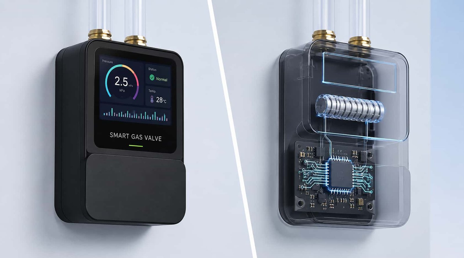
The modern valve keeps the mechanical parts as the last line of defense and adds a board around them. The board carries a microcontroller, a communication module, and one or more pressure sensors. This is where the pressure sensor earns the label sensing core.
The most common sensing architecture uses multiple pressure measurement points inside and around the valve. One sensor measures ambient atmospheric pressure. A second measures the supply pressure upstream of the valve. A third measures the pressure downstream, on the stove side. The firmware compares these numbers.
Overpressure and underpressure are judged from the upstream pressure relative to ambient. If the supply side reads far above or far below where it should be, the controller commands the valve closed. Overflow is judged differently, from the pressure drop between the upstream and downstream points. At normal low flow, the two sides sit close together. When flow spikes, the pressure drop across the valve grows, and that growth is the signature the firmware looks for.
Digitizing the fault state changes what the network can do with a cut-off event. The valve can report its own status over the network, with a timestamp and a diagnosis. The gas company no longer needs to knock on doors. It sees, in a dashboard, which valves cut, when, and which fault class triggered them.
This is the point of the sensing core. A mechanical valve is a switch that closes. An electronic valve with a pressure sensor is an instrument that observes, decides, reports and, only at the end, acts. The sensor is the difference between those two things.
Why Is Micro-Leak Detection the Hard Problem?
The scenario that separates a good sensing core from a mediocre one is micro-leak detection. This is where the sensor, not the valve mechanics, decides whether the product works.
The method is called pressure decay, and it is simple in principle. Close the valve. Seal the downstream section of pipe. Watch the pressure. If gas is escaping anywhere in that sealed section, the pressure will fall. Measure how fast it falls, and you can estimate the leak rate.
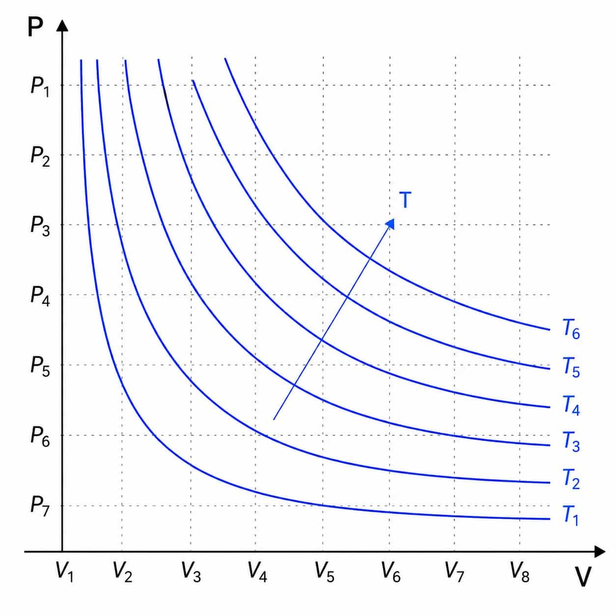
The math is friendly for a microcontroller. After the valve closes, the sealed pipe section holds a fixed volume of gas at roughly room temperature. Treat it as an ideal gas. The amount of gas in the section is proportional to pressure times volume over temperature. Volume is constant, temperature changes slowly, so the pressure is directly proportional to the amount of gas. The rate of pressure decay is therefore directly proportional to the leak rate. The microcontroller differentiates the pressure reading over time and compares the slope to a threshold.
Some implementations formalize this with a leak-rate estimate. Right after the valve closes, the pressure is still at supply level and the decay slope is at its steepest. The gas leak rate at that moment can be computed from the pressure derivative, and the volume leak rate follows from the ideal gas law. If the slope exceeds the threshold, the firmware declares a leak and keeps the valve shut. If not, it reopens and goes back to normal operation.
Now the difficulty. A leak of tens of milliliters per hour, in a pipe section maybe a meter long and a few millimeters wide, produces a pressure fall of only a few pascals per second, or even less. A pascal is a tiny unit. Atmospheric pressure is about 101,325 pascals. The sensor is being asked to resolve changes a few thousandths of a percent of atmospheric pressure, on top of a baseline of only a couple of kilopascals, in a kitchen where the stove is radiating heat and the window draft is moving air.
Engineers working on the sealing side of gas systems classify leaks by the physics that drives them. A crack or seam under low pressure leaks in a laminar, pressure-driven regime, where the leak rate grows with the square of the pressure drop through the narrow path. A larger break flows in a turbulent regime with a different pressure-flow relation. And a component like an aged rubber hose can leak by diffusion, where gas molecules migrate through the material itself with no visible opening at all. Each regime leaves a different signature in the pressure-decay curve. A sensor that resolves the slope, not just the level, gives the firmware a chance to tell a failing seal from a deteriorating hose. None of that is possible with the mechanical mechanism alone.
That is why sensor resolution and relative accuracy dominate the selection process. If the sensor can only resolve ten pascals, the pressure-decay slope from a slow leak is buried in the noise and the firmware will misread it. If it can resolve a pascal or better, the slope shows up as a clean, repeatable signal.
Micro-leak detection range on commercial products lands in the 0 to 20 milliliters per hour territory. That is the sensitivity budget the sensing core has to meet. A MEMS piezoresistive sensor with a high-resolution analog-to-digital converter, typically 24-bit, is the practical way to get there. The mechanical valve, no matter how cleverly the spring is tuned, cannot see it. This one function alone justifies the electronics.
Sampling strategy deserves its own paragraph, because it is where projects usually get the slope wrong. A naive implementation reads pressure once a minute, subtracts consecutive values, and calls the difference a leak rate. The problem is that each reading carries noise, and subtracting two noisy values doubles the noise while the real slope is tiny. The better approach is to burst-sample at a fast rate for a short window right after closure, fit a line to the samples, and read the slope of the fit instead of the difference of two points. The fit averages out the sensor noise and leaves the true decay rate. Most implementations also discard the first few hundred milliseconds while the closing transient and residual flow settle. With a 24-bit sensor and a tight burst, a slope of a few pascals per second is resolvable and repeatable. That is the difference between a feature that demos well and one that survives a field audit.
What "AI" Actually Means in a Gas Valve
The word AI gets thrown around loosely, so it is worth being precise about what it means in this product category. There is no large language model inside a gas valve, and there does not need to be. The intelligence is rule-based and statistical, and it lives in the firmware that consumes the pressure data.
The everyday behavior is already useful. The valve can learn the pattern of a cooking session. When the stove is lit, the firmware sees the flow and pressure signature and opens the valve if it was closed. When the flame goes out and flow stops, it closes the valve behind it. The user never touches it. Elderly people who forget to turn off the burner are protected, because the valve is watching flow duration and pressure the whole time.
Picture the common case this product exists for. An elderly person lives alone. They light the stove, the valve opens automatically, they cook, and they walk away to the television while the burner stays on. The valve has been watching flow duration, and the pressure signature tells it that the burner has run long past any reasonable meal. It closes the gas off at the source. No smoke alarm is involved, because the valve acts on what it measures rather than on what a detector happens to smell. The sensor data, not the mechanical trip, is what made that decision possible.
The deeper use of the data is fault localization. A single underpressure report from one apartment suggests a problem in that apartment, most likely the hose or the appliance. Underpressure reports from dozens of apartments in one building at the same moment point to the building's supply line or the network beyond it. The cloud platform compares reports across units and points the maintenance crew at the right segment before they leave the depot. The same sensor-driven logic that makes smart gas meters report remotely applies to the valve on the other side of the pipe.
There is also the post-close inspection I mentioned earlier. After the valve closes for any reason, it can re-check. Hold the downstream section sealed, watch the pressure decay, and decide whether the cause of the trip is gone. A valve that self-tests like this is doing what a good technician does, but it does it unattended, on schedule, at every relevant moment.
None of this works if the pressure numbers are wrong. The whole chain, from open-on-ignition to building-level fault localization, is only as good as the sensor at the front of it. That is the concrete meaning of sensing core in this product. The eyes come first, and the brain is downstream of them.
What Sensor Specs Actually Matter Here
Every gas valve company that calls us eventually asks the same question. What pressure sensor should I put in my valve? Here is what we actually tell them.
Pressure range, and the temptation to oversize
The working pressure at the stove is around 2 to 3 kPa of gauge pressure. The overpressure trip sits around 8 kPa. On top of that sits atmospheric pressure, roughly 101 kPa at sea level. A sensor that covers the atmospheric baseline plus the trip point with comfortable margin — call it 0 to 130 kPa absolute, or thereabouts — sees all of that without throwing resolution away. The mistake is going much larger. If you fit a sensor rated for a few hundred kilopascals, your 3 kPa signal occupies less than one percent of full scale, and you throw away most of your resolution before the ADC sees it. Buy range that fits the application. Oversized range is a quiet way to ruin micro-leak sensitivity.
The other range consideration is what happens above the trip point. The sensor should survive, without damage or calibration shift, whatever pressure the supply can deliver before the valve physically closes. Absolute vs gauge matters here too, and it is covered below.
Resolution and relative accuracy beat full-scale percentage
This is the single most underrated spec in this application. Datasheets love to print full-scale accuracy, like plus or minus 1 percent of full scale, because it is a single tidy number. For micro-leak detection that number is nearly meaningless. What matters is relative accuracy, the smallest pressure change the sensor can resolve reliably.
The difference between resolving 1 pascal and resolving 10 pascals is the difference between detecting a slow leak and not detecting it. A sensor with plus or minus 0.03 hPa relative accuracy, which is 3 pascals, is in the class that can separate a real leak slope from normal drift. Getting to that pascal-level resolution is exactly what separates a barometer that works for micro-leak detection from one that does not. When a spec sheet gives you full-scale accuracy and noise figures, convert everything to pascals at your operating pressure. That is the number that decides the product.
Power, because the valve lives on a battery
A household gas valve has no wall outlet handy and no one wants to change batteries every quarter. The system budget is microamps. The sensor's operating current and, especially, its standby current, determine how often the valve can afford to take a reading and how long the battery lasts.
Operating current in the single-digit microamp range and standby current under a microamp are the targets. With duty-cycled sampling and a low-power wide-area network like NB-IoT for the occasional status report, a ten-year battery life is achievable. If the sensor idles at milliamps, the whole ten-year story falls apart no matter how good the rest of the board is.
Temperature, the kitchen is an adversarial environment
The sensor sits near a stove. The kitchen goes from a cold morning to a hot frying pan in minutes. Pressure readings drift with temperature in two ways. The gas itself changes density, and the sensor's own bridge and amplifier have thermal coefficients.
On-chip temperature compensation is not optional here. The sensor should measure its own temperature and apply correction, ideally outputting temperature alongside pressure so the firmware can sanity-check the pressure-decay slope against thermal drift. A kitchen draft that changes the sensor temperature by a couple of degrees can produce a pressure-slope artifact that looks exactly like a micro-leak. The combination of a compensated sensor and a temperature-aware algorithm is what keeps false alarms low.
Long-term stability and sealing
The valve is installed and expected to work for a decade. The sensor has to hold its calibration over years of temperature cycling, vibration from doors slamming, and the humid air of a kitchen. In a non-corrosive gas environment, Langdurige stabiliteit is what keeps the drift curve flat instead of creeping toward a false trip. Package-level environmental protection matters too. A sealed lid over the sensing element keeps moisture and contaminants off the fragile silicon so the sensor does not drift quietly toward a false trip or a missed leak.
Interface and integration
I2C or SPI, whichever the host controller already speaks. A 24-bit ADC on the sensor chip means the resolution work is done at the sensor and the microcontroller is not left to coax millivolts out of a raw bridge. Small package footprints matter in a valve body that is also holding a mechanical actuator and a communication module. In practice this means an LGA or similar surface-mount package that can be reflowed and sealed into the assembly.
Here is the summary we hand out in one table.
A 1 Bar Sensor That Fits the Application
Here is where our own hardware fits, and the honest reason is that the range matches the job rather than fighting it.
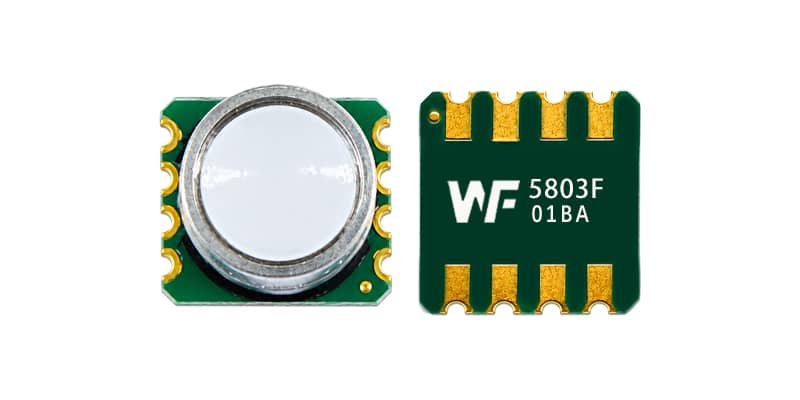
The WF5803F is a family of digital barometers built on the same piezo-resistive MEMS die. The version that belongs in a gas valve is the 1 bar part, not the 7 bar part. Its operating range is 10 to 1300 hPa. A gas stove line sits at an absolute pressure of roughly 1020 to 1040 hPa — atmospheric pressure plus the 20 to 30 hPa of gauge pressure at the stove inlet. That sits comfortably inside the sensor's range, with headroom for the overpressure trip. The sensor is not working at a fraction of a percent of full scale; it is operating in the middle of a range that was sized for the job.
The specs that matter for micro-leak detection carry over directly:
- Relative accuracy of plus or minus 0.03 hPa. That is the 3 pascal class that separates a real leak slope from noise, the spec the entire micro-leak story rests on.
- A 24-bit ADC on the die. The resolution work is done at the sensor; the microcontroller reads a digital value instead of coaxing millivolts out of a raw bridge.
- Absolute accuracy of typically plus or minus 1.5 hPa over the compensated range.
- About 3.5 microamps active at a 1 Hz sampling rate, and 0.3 microamps in sleep. The numbers that make a ten-year battery story work.
- I2C and SPI, an on-chip temperature sensor with a 1.5 Pa/K offset coefficient, and an operating span of minus 40 to plus 125 degrees Celsius.
- An 8-pin metal-lid LGA package, 6.2 by 6.8 by 3.3 millimeters, that reflows onto a compact valve board.
The earlier point about not oversizing the range is exactly the difference between the 1 bar and 7 bar parts. The 7 bar version of the same die is a fine sensor, but in a gas valve it would be working at a tiny fraction of its span, throwing away most of its usable resolution. The 1 bar version keeps the same plus or minus 0.03 hPa relative accuracy while operating in the middle of a range that fits the application. Same die, same interface, same firmware library, same supply chain — different range. Choose the one that matches the pipe, not the one that matches a different product's road map.
If your design already carries the WF5803F for another application — drones, wearables, weather stations, industrial transmitters — the gas valve is a natural add-on instead of a new qualification project. The qualification, the firmware library and the calibration flow all travel with the part.
A quick honesty note on ranges. If you are building a valve-only product and optimizing purely for cost, a part with an even tighter range matched to the application is a legitimate choice, and we can talk about that too. The 1 bar part earns its place because it combines the right resolution with a range that covers the atmospheric baseline, the trip point, and the rest of a broader product portfolio in one qualified component.
Design and Integration Notes from the Field
A good sensor in the wrong integration fails anyway. These are the details that separate valves that work in production from valves that work in the lab.
Pressure port placement
The sensor must see the pressure you intend to measure and nothing else. Condensation is the classic killer. If the port faces upward, moisture collects in it and eventually reaches the sensing element. Route the port downward or sideways, and give the firmware a reason to distrust readings that jump along with the stove cycling.
Sample the slope, not just the level
For micro-leak detection, take a short burst of samples right after the valve closes, fit the pressure decay, and reject the first few samples while the flow transients settle. The derivative is where the signal lives. Averaging the absolute level smooths out exactly the information you need.
Calibrate at install, and re-zero after temperature steps
Every installed valve sits at a slightly different elevation and sees a slightly different local atmospheric pressure. A one-time reference reading at installation gives the firmware a local zero. When the kitchen temperature makes a step change, allow the algorithm to re-baseline before it starts judging leak slopes, or a hot pan going on the stove will read as a false leak.
Watch the electromagnetic noise
A solenoid valve actuation is a current spike, and a relay clicking is a small spark. Both couple into sensitive analog lines. Keep the sensor's traces short, route them away from the actuator coil, and give the sensor a clean supply that does not sag when the valve slams shut. A sensor that reads correctly during a cooking session but glitches during its own actuation is worse than no sensor, because it produces trips with no cause.
Consider a second sensing path for the highest-safety tiers
The most serious valve designs carry the mechanical cut-off as the fail-safe and the electronic path as the primary observer, and some add a second, independent pressure reading for cross-check. Two readings that agree confirm the event. Two readings that disagree flag a sensor fault instead of a gas event. For gas utility deployments that want evidence for every shut-off, that audit trail is worth the extra part.
Why Keep the Mechanical Core If You Have Electronics?
There is a design philosophy in this product category that is worth respecting. The electronics add capability, but the mechanical core is the safety net, and the two are deliberately kept independent.
If the battery dies, the firmware hangs, or the sensor drifts out of tolerance, the valve must still protect the house. Because the mechanical parts do not depend on the electronics, the valve keeps cutting on gross overpressure, underpressure and overflow even with the board dead. The electronic path adds the diagnosis, the micro-leak detection and the network reporting on top. This is redundancy with different failure modes, which is the strongest kind. A mechanical failure and an electronic failure would have to coincide, in opposite directions, for the protection to be lost.
For a sensor vendor this philosophy has a practical consequence. The sensor has to be good enough that its failures are rare and visible, because the system treats a silent sensor fault as a reason to fall back to mechanical operation, and a misreporting sensor as a reason to distrust the whole electronic path. Consistency and calibration retention matter more here than in almost any other consumer application.
What Certifications Does a Smart Gas Valve Need?
Getting a gas safety valve certified is its own project, and the sensor spec is written into it. Explosion-proof designs carry ratings in the Ex ib category, meaning the electronics are intrinsically safe and cannot release enough energy to ignite gas even in a fault. Operating temperature for household units commonly spans minus 20 to plus 60 degrees Celsius, which sounds easy until you remember the sensor sits beside a stove in both winter and summer. Service-life expectations run to ten years and beyond.
The sensor that goes into such a product has to survive the qualification process, hold its calibration across that temperature span, and still be available at production volume years later. A sensor that drifts over a five-year soak test fails the product as surely as a mechanical latch that sticks. Long-term stability is not a luxury spec in this application. It is a certification requirement wearing a datasheet costume.
The regulatory backdrop matters too. Requirements differ by market, and a change to a single safety code can reshape a regional market overnight. Engineers designing these products tend to pick sensors that can ride through multiple product generations and multiple jurisdictions rather than parts that require re-qualification every year. That is one more reason the range and the ecosystem around a sensor family — the firmware, the supply chain, the qualification data — can matter as much as the datasheet numbers.
The Bottom Line
The gas self-closing valve is a small product with a serious job, and the pressure sensor is the part that determines how well it does that job. The mechanical core keeps the house safe in a blackout. The sensor decides whether the valve is a dumb switch or a device that sees a slow leak, reports a real cause, and locates a fault across a whole building before anyone walks to the door.
If you are designing one of these valves, or choosing the sensor for a valve already on your bench, start from the sensing requirements, not from habit. Resolve the pascal at your operating pressure. Keep the standby current under a microamp. Compensate for the kitchen. Protect the package. Pick a range that fits the application and the rest of your portfolio. That is the sensing core, and everything else is downstream of it.


