Կատալոգ
Laparoscopic procedures create an operative space by insufflating the abdominal cavity with CO₂. An insufflator must provide a supply able to reach 150 mmHg at the source, while stabilising cavity pressure in the 3–25 mmHg range for standard/gynaecology/urology modes or 3–20 mmHg for infant mode. The design should also include a 30 mmHg measurement point for converting pressure to flow using mechanical relations. Key engineering requirements are fast response, long-term stability, temperature compensation and tolerance for moist or contaminated gases.
1: Design principles and system requirements
The starting point for multi-stage monitoring and performance thresholds
Patient safety comes first. The insufflator should place sensors at the gas source and at key points near the cavity so the system can close the loop between a supply pressure (about 150 mmHg) and the target cavity pressure (3–25 or 3–20 mmHg). Keep a dedicated 30 mmHg point for flow estimation. Required performance includes fast response (typical ≤ 3 ms), long-term stability (drift controllable to around ±0.25% FSL per year), temperature compensation and factory calibration. The sensor must handle humidity, traces of contaminants and mildly corrosive fluids. Hardware should run on 5 V with a proportional voltage output for straightforward, cost-effective mass production and integration.

2: Key sensor selection criteria
Why choose temperature-compensated, calibrated MEMS sensors
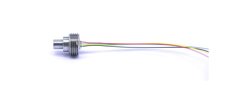
Choosing MEMS sensors with temperature compensation and factory calibration reduces software burden and improves accuracy. Sensors must be compatible with gas and liquid contact and remain stable in contaminated water, steam or mildly corrosive media. Prioritise 5 V operation, proportional voltage output, fast response (~3 ms), integrated temperature reading with about 11-bit resolution (temperature error near ±3 °C), and long-term stability around ±0.25% FSL per year. Robust ASIC packaging that tolerates 2× overload and 5× burst pressure adds safety margin.
3: Multi-stage monitoring architecture and implementation
From sensor placement to flow conversion: practical engineering points
Architecturally, fit a high-pressure sensor near the CO₂ supply to monitor the ~150 mmHg source, and low-pressure sensors near the cavity inlet to measure the working range (3–25 mmHg or 3–20 mmHg). Use a 30 mmHg test point and a mechanical model to convert that pressure into instantaneous flow and volumetric rate. Sampling must support high rates and low latency during critical operations. Signal conditioning should include amplification, anti-aliasing low-pass filtering, differential measurement and temperature compensation. Reserve a calibration channel for in-field checks and store calibration factors for traceability.
4: Signal processing and safety logic
Signal and logic design to ensure safe control loops
Use a high-resolution ADC together with temperature correction and linearisation routines. Implement dynamic filtering and baseline drift detection to reduce false alarms. The system should have sensor redundancy and consistency checks; if readings diverge, switch to a safe mode and trigger visual and audible alerts. Control logic needs hard limits (upper and lower bounds), over-pressure shut-off, abnormal flow detection and watchdog timers. Log critical events for audit and compliance.
5: Engineering recommendations and cost-effectiveness
Hardware integration and maintenance suggestions for volume production
For low-cost, high-volume medical gas products, use rugged ASIC-packaged MEMS sensors, standardised 5 V proportional outputs, built-in temperature sensing and modular sensor sockets for easy replacement. PCB layout should include shielding and clear grounding zones; pressure ports should be metal-isolated or sealed with inert materials to extend service life. Factory calibration and verification will help keep system stability near ±0.25% FSL per year, reducing field maintenance and total cost of ownership.
Եզրափակում
A practical multi-stage monitoring solution for medical insufflators combines temperature-compensated, factory-calibrated MEMS sensors with fast response, contamination tolerance and a system-level safety architecture. Integrating WF152D-style rugged sensors, 5 V proportional outputs and a careful sensor layout with solid signal processing and redundancy yields a reliable, manufacturable system that meets both adult and infant insufflation requirements.
Վերոնշյալ ներածությունը միայն քերծում է ճնշման սենսորային տեխնոլոգիայի կիրառությունների մակերեսը: Մենք կշարունակենք ուսումնասիրել տարբեր արտադրատեսակներում օգտագործվող սենսորային տարրերի տարբեր տեսակները, ինչպես են դրանք աշխատում, ինչպես նաև դրանց առավելություններն ու թերությունները: Եթե ցանկանում եք ավելի մանրամասն մանրամասնել, թե ինչ է քննարկվում այստեղ, կարող եք ստուգել համապատասխան բովանդակությունը ավելի ուշ այս ուղեցույցում: Եթե դուք սեղմված եք ժամանակի համար, կարող եք նաև սեղմել այստեղ՝ այս ուղեցույցի մանրամասները ներբեռնելու համար Օդային ճնշման ցուցիչի արտադրանք PDF տվյալներ.
Այլ սենսորային տեխնոլոգիաների մասին լրացուցիչ տեղեկությունների համար խնդրում ենք Այցելեք մեր տվիչների էջը.