- Door WF-sensoren
Een direct bandenspanningscontrolesysteem meet de druk in elke band met sensoren die op het wiel zijn gemonteerd en verzendt die gegevens draadloos naar een ontvanger in de cabine. Vergeleken met indirecte systemen kan het voor elke band de momentane absolute druk weergeven. Gevoeligheid en resolutie bepalen of het systeem vroeg genoeg waarschuwt. Dit artikel richt zich op de manier waarop piëzoresistieve druksensoren worden geïmplementeerd in TPMS, en belicht drie kernproblemen: sensorresolutie, temperatuurafwijkingsregeling en beheer van energieverbruik.
Catalogus
1. Inleiding tot directe bandenspanningscontrolesystemen
Een direct systeem plaatst sensoren in elk wiel direct meten bandenspanning en verzendt deze metingen vervolgens draadloos naar een ontvanger in de cabine. De kracht ervan is het leveren van de onmiddellijke absolute druk voor elke band, met een hoge detectienauwkeurigheid, zodat hij kan waarschuwen voor kleine lekkages of drukdalingen. Indirecte systemen daarentegen vertrouwen op de ABS-wielsnelheidssensoren van het voertuig om verschillen in rotatiesnelheid tussen banden te detecteren; deze aanpak kan geen werkelijke momentane drukwaarden rapporteren, en er wordt geen alarm gegeven als banden op dezelfde as of het hele voertuig tegelijkertijd druk verliezen. Directe systemen vallen doorgaans in twee groepen: actieve modules op batterijen en passieve modules (vaak gebruikmakend van akoestische oppervlaktegolven, SAW, technologie) waarvoor geen batterij nodig is. Actieve modules zijn volwassen en flexibel in signaalverwerking, maar worden beperkt door de levensduur van de batterij; passieve ontwerpen besparen energie, maar vereisen standaarden en integratie op het niveau van de bandenfabrikant om praktisch te zijn.
Systeemtypen en vergelijking
Actieve systemen combineren piëzoresistieve of capacitieve MEMS-druksensoren met een radiomodule met laag vermogen, waardoor hoge bemonsteringsfrequenties en directe metingen worden geboden. Passieve systemen maken doorgaans gebruik van SAW-sensoren die akoestische oppervlaktegolven veranderen als reactie op druk; ze hebben een RF-ondervrager nodig en hebben geen boordvoeding nodig. Bij de keuze tussen deze moet u realtime prestaties, levensduur en implementeerbaarheid afwegen.

2. Hoe piëzoresistieve druksensoren werken in TPMS
Piëzoresistieve sensoren worden gemaakt met behulp van silicium MEMS-processen die resistieve elementen op een diafragma plaatsen. Toegepaste druk vervormt het diafragma en verandert die weerstanden; die verandering wordt met een Wheatstone-brug of differentiële versterker omgezet in een spanning. Deze aanpak is eenvoudig, het lineaire bereik kan in de signaalketen worden gecorrigeerd en siliciumverwerking zorgt voor een goede batchconsistentie. Voor bandengebruik zie je doorgaans waarden van 0–7 bar (of lager voor personenauto's). Ontwerpdoelen zijn gericht op hoge resolutie (om kleine drukveranderingen te detecteren), lage temperatuurdrift en sterke schok-/trillingsbestendigheid.
Van middenrifspanning tot weerstandsverandering
Diafragmadikte, de lay-out van rekstrookjes en hun plaatsingscontrolegevoeligheid en volledige output. Technische keuzes moeten de geometrie en procesparameters in evenwicht brengen om de vereiste resolutie te bereiken en tegelijkertijd de stabiliteit over het hele temperatuurbereik te behouden. Voor bandenmonitoring is doorgaans een resolutie beter dan ongeveer 0,05 bar nodig om kleine lekkages betrouwbaar te kunnen detecteren.
3. Basisprincipes van sensorontwerp en verpakking
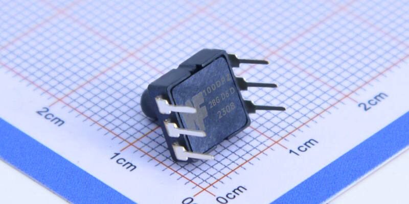
De wielomgeving stelt sensoren bloot aan zware trillingen, hoge temperaturen en vocht, dus de verpakking is van cruciaal belang. Het apparaat in WF162F-stijl dat in de afbeelding wordt weergegeven, heeft een topdrukpoort en meerdere soldeervlakken op een SMD-voetafdruk; een metalen kap gekoppeld aan een SMD-substraat kan mechanische sterkte bieden en tegelijkertijd een drukinlaat bieden. Verpakkingsmaterialen moeten bestand zijn tegen zoutnevel en herhaalde schokken; de drukpoort moet zo zijn ontworpen dat verstopping door stof of vuil wordt voorkomen en moet passen bij het montagegat van de velg. Elektrisch gezien moeten de pads bestand zijn tegen vermoeidheid en robuuste grond- en stroomretourpaden bieden.
Keuzes voor drukpoorten en verpakkingsmateriaal
De drukpoort moet de interne druk nauwkeurig overbrengen en tegelijkertijd weerstand bieden aan deeltjesblokkeringen; een metalen kap met een polymeerbasis geeft vaak de juiste mix van afdichting en mechanische sterkte. Bij de materiaalkeuze moet rekening worden gehouden met de thermische uitzettingscoëfficiënten en het werktemperatuurbereik om mismatches te voorkomen die drift bij extreme temperaturen veroorzaken.
4. Signaalconditionering en draadloze transmissie
De ruwe spanning van een piëzoresistieve sensor moet worden versterkt, gefilterd, omgezet in digitaal en temperatuurgecompenseerd voordat een microcontroller en een RF-blok met laag vermogen deze kunnen verzenden. Belangrijke stappen zijn onder meer het matchen van een ruisarme versterker met een ADC met hoge resolutie en het toepassen van realtime temperatuurcorrectie. Draadloze verbindingen maken vaak gebruik van Bluetooth Low Energy of gepatenteerde RF, en de antenne-indeling en instellingen voor zendvermogen moeten de betrouwbaarheid van de verbinding in evenwicht brengen met de levensduur van de batterij.
A/D, temperatuurcompensatie en energiebeheer
Hoge nauwkeurigheid profiteert van een ADC met hoge resolutie (vaak 24-bit of vergelijkbaar nauwkeurig) gecombineerd met digitale filtering om ruis te verminderen. Temperatuurcompensatie kan een eenvoudige eerste-orde-correctie zijn of een opzoektabelbenadering om de drift over de bedrijfstemperaturen te beperken. Voor actieve modules zijn energiebeheertechnieken zoals slaapcycli, gebeurtenisgestuurde sampling en energiezuinige wake-modi essentieel om de levensduur van de batterij te verlengen en tegelijkertijd de meetbetrouwbaarheid te behouden.
5. Prestatiestatistieken, testmethoden en betrouwbaarheidsvalidatie
De belangrijkste meetgegevens van de TPMS-sensor omvatten absolute nauwkeurigheid, resolutie, lineariteit, temperatuurcoëfficiënt (mbar/°C of ppm/°C), drift op lange termijn en trillingstolerantie. Validatie vereist testen in temperatuurkamers, trilinstallaties en vochtkasten en het uitvoeren van meerpuntskalibratie tegen een drukstandaard. Testen op systeemniveau moeten ook het draadloze pakketverlies, de gevoeligheid van de ontvanger en het aantal valse alarmen meten.
Standaardtests en omgevingsstress
Een standaard testregime omvat meerpuntsdrukkalibratie bij verschillende temperaturen, thermische schokcycli, mechanische trillingen en vochtige-hittetests. Betrouwbaarheidsproeven op lange termijn (bijvoorbeeld versnelde veroudering gedurende 1.000 uur) laten zien hoe verpakkingen en materialen verslechteren onder wegomstandigheden en vormen een leidraad voor verbeteringen in het ontwerp en de garantiestrategie.
Conclusie
Bij het gebruik van piëzoresistieve druksensoren in directe TPMS zijn de technische prioriteiten duidelijk: zorg voor een hoge resolutie met minimale temperatuurafwijking, zorg voor een robuuste behuizing en optimaliseer het draadloze energieverbruik. Apparaten in WF162F-stijl op de foto laten een gemeenschappelijke aanpak zien: SMD-verpakking met metalen dop en een poort aan de bovenzijde die voldoet aan de mechanische behoeften van wielmontage. Uiteindelijk zorgt een productieklaar systeem voor een evenwicht tussen kosten, levensduur en meetnauwkeurigheid, en alleen strenge milieutests en productiekalibratie kunnen een consistente productkwaliteit garanderen. Teams die vroeg investeren in verpakkingsmaterialen, temperatuurcompensatie-algoritmen en energiebeheerstrategieën zullen de risico's op het gebied van onderhoud en terugroepacties op de lange termijn verminderen.
De bovenstaande introductie schetst slechts het oppervlak van de toepassingen van druksensortechnologie. We zullen doorgaan met het verkennen van de verschillende soorten sensorelementen die in verschillende producten worden gebruikt, hoe ze werken en hun voor- en nadelen. Als u meer informatie wilt over wat hier wordt besproken, kunt u de gerelateerde inhoud verderop in deze handleiding bekijken. Als u weinig tijd heeft, kunt u ook hier klikken om de details van deze handleidingen te downloaden Luchtdruksensorproduct PDF -gegevens.
Voor meer informatie over andere sensortechnologieën kunt u terecht Bezoek onze sensorenpagina.