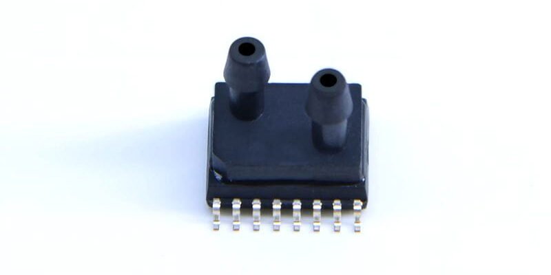
- Door WF-sensoren
Classification of MEMS Pressure SensorsMEMS
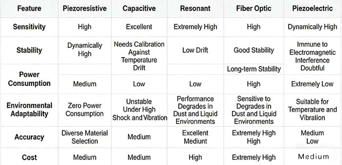
The fundamental differences among MEMS pressure sensors arise from the physical effects they exploit. Different operating principles define their performance envelopes and suitable application domains. The mainstream technological approaches comprise five categories: piezoresistive, capacitief, resonant, fibre-optic En piezoelectric sensors. These technologies exhibit marked differences in characteristics and trade-offs.
1. Piezoresistive Pressure Sensors
Piezoresistive sensors are based on the piezoresistive effect discovered in 1954 — when a semiconductor material (such as single-crystal silicon) is stressed, changes in its band structure produce measurable changes in resistivity.
The typical construction features a silicon diaphragm coupled with a Wheatstone bridge: the diaphragm is edge-clamped and sealed, with an inverted pyramidal cavity formed by backside etching. Four piezoresistive elements are diffused on the diaphragm surface to form the bridge.
When pressure is applied the diaphragm deforms, causing one pair of bridge resistances to increase while the other pair decreases; the output is a voltage signal that is linear with pressure. To improve performance the sensor die is usually bonded to a glass substrate with matched coefficient of thermal expansion, providing stress isolation and electrical insulation. Piezoresistive sensors are simple in structure and low in cost, and are well suited to mass production — however, they require temperature compensation to mitigate environmental effects.

2. Capacitive Pressure Sensors
Capacitive sensors operate on the parallel-plate capacitor principle: a movable silicon diaphragm serves as one electrode and a fixed electrode forms the other, with pressure-induced diaphragm deflection changing the electrode spacing and hence the capacitance. Typical structures comprise a circular metal-coated diaphragm (or metalised silicon diaphragm), a stationary electrode and a cavity; measurement electronics translate capacitance changes into electrical signals.
Compared with piezoresistive sensors, capacitive types generally offer superior sensitivity and linear range, and lower temperature drift with higher stability. They do, however, require electrode insulation; presence of particulates or liquids can interfere with measurement, and manufacturing costs are relatively higher. In many implementations the silicon-to-glass bond is used to form a vacuum reference cavity, making capacitive sensors suitable for absolute pressure measurement.
3. Resonant Pressure Sensors
Resonant sensors exploit the stress–frequency relationship: the natural resonance frequency of a resonator (for example a silicon beam or membrane) shifts in response to stress induced by applied pressure. Typical resonant elements include double-ended tuning forks (DETF) or resonant membranes; dedicated drive and detection circuitry sustain oscillation and read frequency shifts.
Resonant sensors excel in precision and resolution, often providing a digital frequency output that interfaces easily with digital systems. Their downsides are more complex manufacturing, longer production cycles, and sensitivity to temperature and mechanical vibration — all of which contribute to higher cost. Accordingly, resonant sensors are chiefly used in high-end applications such as aerospace and metrology.
4. Fibre-optic Pressure Sensors
Fibre-optic sensors commonly use Fabry–Pérot interferometry: one end of an optical fibre forms a semi-reflective surface while a movable membrane serves as the other reflector; changes in membrane position alter the optical path difference and the resulting interference fringes, from which pressure can be inferred. Core components include the optical fibre, reflective membrane and a sealed cavity.
Advantages of fibre-optic approaches include intrinsic immunity to electromagnetic interference and suitability for high-temperature, corrosive or otherwise harsh environments, as well as compactness and remote sensing capability. However, optical components are costly, system alignment and commissioning are complex, and the fibre-to-membrane assembly requires exacting fabrication processes — factors that limit large-scale deployment.
5. Piezoelectric Pressure Sensors
Piezoelectric sensors rely on the piezoelectric effect: certain materials (e.g. aluminium nitride (AlN), lead zirconate titanate (PZT)) generate charge under mechanical stress. A typical structure is a piezoelectric film or ceramic; these devices produce a charge output without an external power supply, making them effectively self-powered.
Piezoelectric sensors have excellent dynamic response (millisecond-scale), making them ideal for transient pressure monitoring (explosions, shocks, impulses). They cannot measure static pressure reliably, their output signals are typically small and require complex amplification and conditioning, and their long-term stability can be inferior to other types.
| Type | Core Concept | Internal Structure |
|---|---|---|
| Piëzoresistief | Semiconductor piezoresistive effect; resistance changes with stress | Silicon elastic diaphragm + diffused piezoresistors (Wheatstone bridge) |
| Capacitief | Parallel-plate capacitor; capacitance changes with plate spacing | Movable thin-film electrode + fixed electrode + cavity |
| Resonant | Resonator frequency changes with stress | Silicon beam/thin-film resonant element + drive/sense circuits |
| Fiber-optic | Optical path difference causes shift in interference pattern | Optical fiber + half-reflective mirror + movable thin-film reflector |
| Piëzo -elektrisch | Piezoelectric material generates charge under stress | Piezoelectric thin film/ceramic plate + electrodes |
Comparison of Principles and Structures
- Descriptive comparison summarised above:
- piezoresistive — Wheatstone bridge with diffused resistors on a silicon diaphragm;
- capacitive — parallel-plate capacitor with vacuum reference; resonant — frequency shift of resonator elements;
- fibre-optic — Fabry–Pérot interference;
- piezoelectric — charge generation in piezo materials.
Performance Comparison
1. Sensitivity
Piezoresistive: High sensitivity suitable for many industrial uses.
Capacitive: Higher sensitivity and wider linear range than piezoresistive.
Resonant: Extremely high sensitivity for precision measurement.
Fibre-optic: High sensitivity with strong immunity to electromagnetic interference.
Piezoelectric: Outstanding dynamic sensitivity but poor static performance.
2. Power Consumption
Piezoresistive: Moderate (mA range); continuous excitation required for bridge operation.
Capacitive: Low (μA range); measurement circuitry does not demand high currents.
Resonant: Relatively high (mA range); oscillator drive is required.
Fibre-optic: Very low; suitable for remote, low-power monitoring.
Piezoelectric: Zero power for the sensing element itself (self-powered); only signal conditioning consumes power.
3. Environmental Robustness
Operating temperature range (general ranking): Piëzo -elektrisch > Fibre-optic > Resonant > Piezoresistive/Capacitive.
Interference immunity: Fibre-optic > Piëzo -elektrisch > Resonant > Capacitief > Piezoresistive.
4. Cost and Integration
Cost (typical): Piëzoresistief < Capacitief < Piëzo -elektrisch < Resonant < Fibre-optic.
Die/chip size: Piezoresistive/Capacitive < Resonant < Fibre-optic.
Toepassingsscenario's
1. Automotive
The automotive sector is the largest single market for pressure sensors, accounting for over 35% of total volume.
Piezoresistive sensors are widely used in engine management, brake systems and tyre pressure monitoring — for example, to measure intake manifold pressure or brake line pressure. Capacitive sensors may be used in comfort systems. Resonant sensors are chosen where higher accuracy is required.
Modern vehicles can contain hundreds of sensors, often including around ten MEMS pressure sensors, supplying critical data to optimise engine performance, improve fuel efficiency and enhance driving safety.
2. Consumer Electronics
With the development of 3D navigation, motion sensing and health tracking, MEMS pressure sensors are increasingly used in consumer devices.
Piezoresistive and capacitive sensors are commonly found in smartphones, tablets and smartwatches as barometers, altimeters and indoor navigation aids. In drones and model aircraft, MEMS pressure sensors provide altitude information that integrates with navigation systems for precise flight control.
3. Medical
MEMS pressure sensors are widely used across medical devices and diagnostic systems.
Capacitive sensors are favoured for blood pressure measurement, ventilators and respirators due to their stability. Piezoresistive types are used for in-vivo pressure monitoring and drug delivery systems because of their high sensitivity.
4. Industrial Automation
In industrial automation, MEMS sensors are used to monitor and control various processes.
Piezoresistive sensors suit liquid and gas pipeline systems and level measurement. Fibre-optic sensors, with strong EMI immunity, are appropriate for harsh industrial environments. Resonant sensors are applied where very high precision control is required.
5. Aerospace
MEMS pressure sensors support aerodynamic testing, high-altitude pressure monitoring, meteorological data collection and pressure control in airborne and space applications. Resonant and fibre-optic sensors are often selected for aerospace roles where high precision and robust anti-interference performance are critical to meeting stringent environmental requirements.
Selection Guide
1. Define the Measurement Objective
Choose the sensor type based on the pressure parameter to be measured:
Absolute pressure sensors: Measure pressure relative to a vacuum reference within the sensor; readings are independent of ambient atmospheric pressure. Suitable for atmospheric pressure and altitude measurements.
Gauge (relative) pressure sensors: Measure pressure relative to ambient atmospheric pressure; suitable for vessel and container pressure where atmospheric variations should be excluded.
Differential pressure sensors: Measure the difference between two pressure ports; used in flow measurement and filtration monitoring.
2. Determine the Pressure Range
Consider the sensor’s maximum overpressure capability, the relationship between accuracy and range, and the cost implications of different ranges:
Maximum overpressure: Pay attention to both static and dynamic overpressure. Dynamic events (pressure spikes) can produce impulsive loads; choose a sensor with adequate overpressure tolerance.
Accuracy vs range: Sensor accuracy often varies with range; selecting an appropriate full-scale range makes it easier to meet accuracy requirements.
Cost vs range: Sensors in the 0.3–1 MPa range are typically less expensive; sensors with ranges below 0.1 MPa or above 1 MPa tend to cost more.
3. Consider Accuracy Requirements
Accuracy depends on nonlinearity, hysteresis, repeatability, temperature effects, zero stability, calibration and humidity.
Define required precision tier:
Ultra-high precision: 0.01–0.1% FS
High precision: 0.1–1% FS
Standard precision: 1–2% FS
Low precision: 2–10% FS
Higher precision sensors carry greater cost and calibration overhead; specify realistic accuracy according to application needs.
4. Electrical Requirements
Output signal formats: MEMS sensors can provide processed digital outputs (I²C, SPI) or analogue outputs (0–5 V, 0–10 V), and current loops (4–20 mA). Choose the interface compatible with your measurement or control system.
Excitation methods: Constant-current and constant-voltage excitation are both used. Constant-current excitation helps compensate thermal sensitivity and is commonly used for precision measurements. Constant-voltage excitation lacks inherent sensitivity temperature compensation but can be compensated externally (for example by adding a thermistor or diode in the bridge). Excitation can also be proportional or fixed, depending on the design requirements.
5. Consider Operating Conditions
Medium type: Gases are compressible; pressure transients can store and release compressive energy and impose impulsive loads on the diaphragm. Liquids are largely incompressible; ensure installation avoids pressure surges that exceed the sensor’s pressure rating.
Environmental conditions: In harsh environments with vibration, shock or strong electromagnetic interference, require enhanced overpressure protection, robust mechanical sealing, secure fastening and electromagnetic shielding and grounding for leads.
Media compatibility: Ensure the diaphragm and wetted materials are isolated from corrosive media where required. For flammable or explosive media, use low excitation currents and increase mechanical protection of the housing.
6. Determine Operating Temperature Range
Typical temperature classifications:
Commercial: −10 to 60 °C
Industrial: −25 to 80 °C
Automotive: −40 to 125 °C
Military: −55 to 125 °C
Specialised: −60 to 350 °C
Select the class appropriate to the application. Wider temperature ranges increase compensation complexity and calibration workload; thermal isolation or mitigation strategies can sometimes allow lower-grade sensors to be used.
7. Pay Attention to Sealing Requirements
Common pressure sealing methods include rubber gaskets, epoxy encapsulation, PTFE (Teflon) gaskets, tapered fitting, pipe thread fittings and welding. The choice of sealing material and method affects the sensor’s operating temperature range and chemical compatibility — select seals that match the expected environment and media.
Conclusie
There are many types of MEMS pressure sensors, each with distinct operating principles, performance characteristics and suitable application domains.
When selecting a sensor, consider the measurement objective, pressure range, accuracy, electrical interface, operating conditions, temperature range and sealing requirements comprehensively to identify the optimal device for your specific application.
With ongoing technological advances, MEMS pressure sensors will continue to see broader application across industries, providing ever stronger support for industrial practice and scientific development.
De bovenstaande introductie schetst slechts het oppervlak van de toepassingen van druksensortechnologie. We zullen doorgaan met het verkennen van de verschillende soorten sensorelementen die in verschillende producten worden gebruikt, hoe ze werken en hun voor- en nadelen. Als u meer informatie wilt over wat hier wordt besproken, kunt u de gerelateerde inhoud verderop in deze handleiding bekijken. Als u weinig tijd heeft, kunt u ook hier klikken om de details van deze handleidingen te downloaden Luchtdruksensorproduct PDF -gegevens.
Voor meer informatie over andere sensortechnologieën kunt u terecht Bezoek onze sensorenpagina.