ລາຍການ
ບົດຄວາມນີ້ສະເຫນີວິທີການນໍາໃຊ້ຂອງການນໍາໃຊ້ເຊັນເຊີຄວາມກົດດັນຢ່າງແທ້ຈິງ MEMS ໃນອຸປະກອນ wearable ເພື່ອວັດແທກລະດັບຄວາມສູງແລະຄວາມເລິກຂອງການດໍານ້ໍາພ້ອມໆກັນ. ການນໍາໃຊ້ເຊັນເຊີ WF282A ເປັນຕົວຢ່າງ, ມັນມີຂະຫນາດນ້ອຍຫຼາຍ, ຄວາມຖືກຕ້ອງສູງ, ແລະພະລັງງານຕ່ໍາ (wfsensors.com). ບົດຄວາມວິເຄາະຄວາມຕ້ອງການແລະຄວາມທ້າທາຍທີ່ແຕກຕ່າງກັນຂອງລະດັບຄວາມສູງທຽບກັບການວັດແທກໃຕ້ນ້ໍາ, ອະທິບາຍຕົວກໍານົດການດ້ານວິຊາການທີ່ສໍາຄັນຂອງ WF282A ແລະຂໍ້ໄດ້ປຽບ, ລວມທັງຄວາມຖືກຕ້ອງສູງ, ການໃຊ້ພະລັງງານຕ່ໍາ, ການຫຸ້ມຫໍ່ແລະການອອກແບບການໂຕ້ຕອບ, ແລະອື່ນໆ. ມັນຍັງສົນທະນາຈຸດສໍາຄັນສໍາລັບການ soldering ແລະ mounting sensor ໃນອຸປະກອນ, ຂັ້ນຕອນການທົດສອບແລະການຄັດເລືອກອຸປະກອນກ່ອນທີ່ຈະການຜະລິດຈໍານວນຫຼາຍ, ແລະຄ່າຊົດເຊີຽລະຫວ່າງ modes-different. ເປົ້າຫມາຍແມ່ນຜູ້ພັດທະນາອຸປະກອນກິລາທີ່ນຸ່ງໄດ້, ບົດຄວາມນີ້ແມ່ນຫຍໍ້ແລະເປັນມິດກັບຜູ້ອ່ານ, ຊ່ວຍໃຫ້ຜູ້ອ່ານເຂົ້າໃຈແລະນໍາໃຊ້ເຕັກໂນໂລຢີເຊັນເຊີຄວາມກົດດັນຢ່າງແທ້ຈິງທີ່ມີຫຼາຍຫນ້າທີ່.
ສິ່ງທ້າທາຍຂອງຄໍາຮ້ອງສະຫມັກຄູ່ຂອງເຊັນເຊີຄວາມກົດດັນຢ່າງແທ້ຈິງ MEMS ໃນການວັດແທກລະດັບຄວາມສູງແລະການດໍານ້ໍາ
ສະພາບແວດລ້ອມການວັດແທກລະດັບຄວາມສູງ
ໃນອາກາດ, ການວັດແທກລະດັບຄວາມສູງສ່ວນໃຫຍ່ແມ່ນອີງໃສ່ການປ່ຽນແປງຄວາມກົດດັນຂອງບັນຍາກາດ. ເມື່ອລະດັບຄວາມສູງເພີ່ມຂຶ້ນ, ຄວາມກົດດັນຫຼຸດລົງປະມານ 1 hPa ຕໍ່ 8 ແມັດ, ຊຶ່ງຫມາຍຄວາມວ່າຫນຶ່ງຊັງຕີແມັດຂອງການປ່ຽນແປງຄວາມສູງເທົ່າກັບປະມານ 0.01 hPa. ດັ່ງນັ້ນ, ການວັດແທກລະດັບຄວາມສູງຕ້ອງການເຊັນເຊີທີ່ມີຄວາມລະອຽດສູງແລະຄວາມຫມັ້ນຄົງຂອງອຸນຫະພູມ. ໃນທາງປະຕິບັດ, ອຸປະກອນມັກຈະປັບຄວາມດັນການອ້າງອິງໃນຕອນເລີ່ມຕົ້ນຫຼືໃນລະດັບສູງທີ່ຮູ້ຈັກ (ໃຊ້ GPS ຫຼືຂໍ້ມູນອ້າງອີງ) ເພື່ອປັບປຸງຄວາມຖືກຕ້ອງ. ອຸນຫະພູມຂອງບັນຍາກາດແລະສະພາບອາກາດເຮັດໃຫ້ຄວາມກົດດັນມີການປ່ຽນແປງ, ດັ່ງນັ້ນເຊັນເຊີຕ້ອງຊົດເຊີຍການປ່ຽນແປງຂອງອຸນຫະພູມແລະຄວາມຊຸ່ມຊື່ນ. ອາກາດແຫ້ງ, ແຕ່ການປ່ຽນແປງດິນຟ້າອາກາດຢ່າງກະທັນຫັນ (ຄືກັບລົມພາຍຸ) ສາມາດລົບກວນການອ່ານໄດ້. ເພື່ອຈັດການການເຄື່ອນໄຫວແນວຕັ້ງຢ່າງໄວວາ (ເຊັ່ນ: ການຂຶ້ນຂັ້ນໄດ), ທ່ານຍັງຕ້ອງການອັດຕາການເກັບຕົວຢ່າງພຽງພໍແລະການກັ່ນຕອງເພື່ອເກັບກໍາການປ່ຽນແປງລະດັບຄວາມສູງແບບເຄື່ອນໄຫວ.
ສະພາບແວດລ້ອມການວັດແທກໃຕ້ນ້ຳ
ພາຍໃຕ້ນ້ໍາ, ເຊັນເຊີແມ່ນຂຶ້ນກັບຄວາມກົດດັນຫຼາຍກ່ວາຢູ່ໃນອາກາດ. ອີງຕາມ NOAA, ຄວາມກົດດັນເພີ່ມຂຶ້ນປະມານຫນຶ່ງບັນຍາກາດສໍາລັບທຸກ 10 ແມັດຂອງນ້ໍາຄວາມເລິກ. ດັ່ງນັ້ນ, ໃນເວລາດໍານ້ໍາ, ການອ່ານເຊັນເຊີຄວາມກົດດັນຢ່າງແທ້ຈິງປະກອບມີທັງຄວາມກົດດັນຈາກຄວາມເລິກຂອງນ້ໍາແລະຄວາມກົດດັນຂອງບັນຍາກາດພື້ນຜິວ. ເຊັນເຊີຕ້ອງຖືກປະທັບຕາແລະກັນນ້ໍາ, ແລະລະດັບການວັດແທກຂອງມັນຕ້ອງກວມເອົາຄວາມເລິກທີ່ຕ້ອງການ. ທ່ານສາມາດບັນທຶກຄວາມກົດດັນກະສານອ້າງອີງ P0 ຢູ່ຫນ້າດິນກ່ອນທີ່ຈະດໍານ້ໍາ, ແລະການນໍາໃຊ້ທີ່ເປັນພື້ນຖານເພື່ອຄິດໄລ່ຄວາມເລິກໃນລະຫວ່າງການດໍານ້ໍາ. ນອກຈາກນັ້ນ, ການປ່ຽນແປງອຸນຫະພູມນ້ໍາແລະຄວາມເຄັມມີຜົນກະທົບຕໍ່ຄວາມຫນາແຫນ້ນຂອງນ້ໍາແລະດັ່ງນັ້ນການຄິດໄລ່ຄວາມເລິກ; ເຫຼົ່ານີ້ສາມາດໄດ້ຮັບການແກ້ໄຂດ້ວຍປັດໃຈການຊົດເຊີຍ. ໃນໄລຍະການດໍານ້ໍາຍາວ, ເຊັນເຊີ drift ຍັງສາມາດແນະນໍາຄວາມຜິດພາດ, ດັ່ງນັ້ນການ recalibration ເປັນໄລຍະຫຼືການແກ້ໄຂສູດການຄິດໄລ່ແມ່ນຈໍາເປັນ.
ຂອບເຂດການວັດແທກແລະຄວາມຕ້ອງການຄວາມຖືກຕ້ອງ
ໃນຮູບແບບລະດັບຄວາມສູງ, ການປ່ຽນແປງຄວາມກົດດັນແມ່ນຫນ້ອຍຫຼາຍ. ສໍາລັບຕົວຢ່າງ, ຄວາມແຕກຕ່າງລະຫວ່າງຄວາມສູງ 3 ແມັດລະຫວ່າງພື້ນແມ່ນເທົ່າກັບປະມານ 30 Pa. WF282A ໃນຮູບແບບຄວາມແມ່ນຍໍາສູງສາມາດສະຫນອງການແກ້ໄຂ ± 0.006 hPa (ປະມານ 5 ຊຕມ), ຕອບສະຫນອງຄວາມຕ້ອງການການວັດແທກລະດັບຄວາມສູງທີ່ເຂັ້ມງວດ. ການວັດແທກຄວາມເລິກຂອງການດໍານ້ໍາຮຽກຮ້ອງໃຫ້ມີລະດັບຄວາມກົດດັນທີ່ກວ້າງກວ່າ: ທຸກໆ 10 ແມັດຂອງນ້ໍາຈືດຈະເພີ່ມປະມານ 1000 hPa. ໃຫ້ສັງເກດວ່າຊ່ວງຂອງ WF282A ແມ່ນ 300–1200 hPa (ປະມານລະດັບຄວາມສູງ 1100 m ຫຼື 10 m ນ້ໍາ), ດັ່ງນັ້ນມັນບໍ່ສາມາດວັດແທກໄດ້ເກີນຂອບເຂດນີ້. ການປ່ຽນແປງອຸນຫະພູມຍັງມີຜົນກະທົບຕໍ່ຜົນຜະລິດຂອງເຊັນເຊີແລະຕ້ອງໄດ້ຮັບການຊົດເຊີຍ.
ການປ່ຽນໂໝດ ແລະສິ່ງທ້າທາຍໃນການອອກແບບລະບົບ
ແອັບພລິເຄຊັ່ນ dual-mode ຕ້ອງການໃຫ້ອຸປະກອນປ່ຽນລະຫວ່າງລະດັບຄວາມສູງ ແລະໂໝດການດຳນ້ຳ. ນີ້ ໝາຍ ຄວາມວ່າລະບົບຈະຕ້ອງກວດພົບວ່າມັນຢູ່ພາຍໃຕ້ນ້ ຳ (ເຊັ່ນ: ຄວາມກົດດັນທີ່ເພີ່ມຂື້ນຢ່າງໄວວາເກີນຂອບເຂດບັນຍາກາດປົກກະຕິ) ແລະເລືອກການຄິດໄລ່ທີ່ ເໝາະ ສົມ. ຍຸດທະສາດທີ່ງ່າຍດາຍແມ່ນການປ່ຽນໄປສູ່ໂຫມດດໍານ້ໍາເມື່ອຄວາມກົດດັນເກີນຂອບເຂດ (ເວົ້າວ່າ 1100 hPa) ສໍາລັບໄລຍະເວລາທີ່ຍືນຍົງ, ເພື່ອຫຼີກເວັ້ນການກະຕຸ້ນທີ່ບໍ່ຖືກຕ້ອງ. ໃນຮູບແບບລະດັບຄວາມສູງ, ສູດບັນຍາກາດມາດຕະຖານປ່ຽນຄວາມກົດດັນເປັນຄວາມສູງ, ໃນຂະນະທີ່ຢູ່ໃນຮູບແບບການດໍານ້ໍາ, ສູດ hydrostatic ແມ່ນໃຊ້ເພື່ອຄິດໄລ່ຄວາມເລິກ. ຄວາມກົດດັນຂອງບັນຍາກາດພື້ນຖານແລະການປັບທຽບແຕກຕ່າງກັນລະຫວ່າງໂຫມດ, ດັ່ງນັ້ນການອອກແບບລະບົບຕ້ອງພິຈາລະນາວິທີການເກັບຮັກສາແລະປັບປຸງຕົວກໍານົດການສະພາບແວດລ້ອມ (ເຊັ່ນ: ຄວາມກົດດັນດ້ານ P0) ເພື່ອຮັບປະກັນການສະຫຼັບທີ່ບໍ່ມີຮອຍຕໍ່. ສະຫຼັບໂໝດຄູ່ມືທາງເລືອກສາມາດສະໜອງໃຫ້ເປັນການສຳຮອງໄດ້.
ຂໍ້ໄດ້ປຽບດ້ານວິຊາການທີ່ສໍາຄັນແລະຂໍ້ມູນຈໍາເພາະຂອງເຊັນເຊີ WF282A
ການປະຕິບັດຄວາມຖືກຕ້ອງສູງ
ເຊັນເຊີ WF282A ສະຫນອງຄວາມຖືກຕ້ອງຂອງການວັດແທກສູງທີ່ສຸດແລະຄວາມລະອຽດ. ໃນຮູບແບບຄວາມແມ່ນຍໍາສູງ, ຄວາມລະອຽດຄວາມກົດດັນຂອງຕົນແມ່ນ ± 0.006 hPa (ປະມານ 5 ຊມຂອງຄວາມສູງ). ຄວາມຖືກຕ້ອງຕາມປົກກະຕິຂອງມັນແມ່ນກ່ຽວກັບການ ±0.12 hPa, ແລະຄວາມຜິດພາດ nonlinearity ແມ່ນປະມານ ±0.06 hPa, ແລະມັນສະຫນອງຜົນຜະລິດດິຈິຕອນ 24-bit ສໍາລັບຄວາມອ່ອນໄຫວທີ່ດີ. ຄວາມລະອຽດສູງດັ່ງກ່າວສາມາດກວດພົບການປ່ຽນແປງຄວາມສູງທີ່ບໍ່ຄ່ອຍສັງເກດເຫັນ.
ການອອກແບບພະລັງງານຕໍ່າ
ການອອກແບບພະລັງງານຕໍ່າຂອງ WF282A ແມ່ນເຫມາະສົມສໍາລັບການໃຊ້ງານແບບພົກພາ. ໂດຍປົກກະຕິຢູ່ທີ່ 1 Hz ການເກັບຕົວຢ່າງປະຈຸບັນແມ່ນປະມານ 2.7 μA; ໃນໂຫມດຄວາມແມ່ນຍໍາສູງປະມານ 60 μA, ໃນໂຫມດພະລັງງານຕ່ໍາພຽງແຕ່ 3 μA, ແລະປະຈຸບັນ standby ຕ່ໍາກວ່າ 1 μA. ຄຸນສົມບັດພະລັງງານຕໍ່າສຸດເຫຼົ່ານີ້ເຮັດໃຫ້ເຊັນເຊີດີເລີດສໍາລັບອຸປະກອນທີ່ໃຊ້ແບັດເຕີຣີທີ່ຕ້ອງການເວລາແລ່ນດົນ.
ການຫຸ້ມຫໍ່ກະທັດລັດແລະທາງເລືອກໃນການໂຕ້ຕອບ

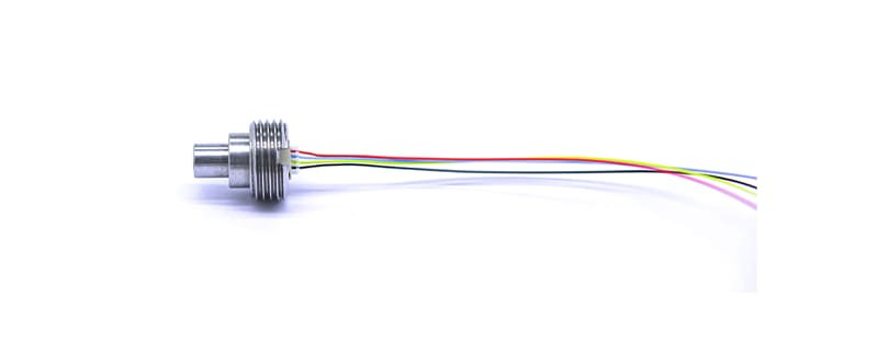
WF282A ມາຢູ່ໃນຊຸດ LGA 8-pad ຂະຫນາດນ້ອຍທີ່ວັດແທກພຽງແຕ່ 2.0 × 2.5 × 0.95 ມມ, ເຮັດໃຫ້ມັນຫນາແຫນ້ນທີ່ສຸດ. ມັນຕິດຕໍ່ສື່ສານກັບເຈົ້າພາບຜ່ານອິນເຕີເຟດ I2C ຫຼື SPI ດິຈິຕອລແລະແມ້ກະທັ້ງສະຫນອງຜົນຜະລິດຂັດຂວາງທາງເລືອກເພື່ອເຮັດໃຫ້ການດຶງຂໍ້ມູນງ່າຍຂຶ້ນ. ມີຂຸມຂະຫນາດນ້ອຍຢູ່ເທິງສຸດຂອງຊຸດທີ່ຮັບໃຊ້ເປັນພອດຄວາມກົດດັນ, ເຊິ່ງຕ້ອງໄດ້ຮັບການຮັກສາໄວ້ຢ່າງຈະແຈ້ງຂອງການອຸດຕັນໃນລະຫວ່າງການອອກແບບແລະການປະກອບ.
FIFO Buffer ແລະການປະມວນຜົນຂໍ້ມູນ
The WF282A includes on-chip FIFO buffering and data processing. Its built-in FIFO can store up to 32 measurement samples, so the host can read multiple values at once and then sleep longer to reduce overall power consumption. The sensor also supports configurable digital filtering (such as IIR filters) and oversampling modes, which suppress noise while maintaining a high sample rate. These internal functions improve measurement reliability and simplify software processing.
Key Points for Soldering and Mounting the Sensor in the Device
Footprint Layout and PCB Design
ໃນເວລາທີ່ການອອກແບບໂຄງຮ່າງ PCB, ໃຫ້ປະຕິບັດຕາມ WF282A ຂອງ 8-pad LGA footprint, ການຈັບຄູ່ຂະຫນາດ pad ກັບອຸປະກອນ. ໂດຍປົກກະຕິ, ປ່ອຍໃຫ້ຊ່ອງເປີດປະມານພອດຄວາມກົດດັນແລະໃຊ້ແຜ່ນ solder-mask ເທິງແຜ່ນເພື່ອປ້ອງກັນບໍ່ໃຫ້ solder ໄຫຼເຂົ້າໄປໃນທ່າເຮືອ. ນອກຈາກນັ້ນ, ຍັງຮັບປະກັນການກໍານົດເສັ້ນທາງໄປຫາແຜ່ນ GND ແລະ VCC ເພື່ອຫຼຸດຜ່ອນຄວາມກົດດັນດ້ານຄວາມຮ້ອນ, ແລະທ່ານສາມາດຕື່ມທອງແດງໃສ່ຊັ້ນໃນເພື່ອຄວາມຫມັ້ນຄົງຂອງຄວາມຮ້ອນທີ່ດີກວ່າ. ຫຼີກເວັ້ນການດັກຖົງ ຫຼືຮ່ອງລະບາຍອາກາດພາຍໃຕ້ເຊັນເຊີ, ເນື່ອງຈາກວ່າອາກາດຕິດຢູ່ສາມາດເຮັດໃຫ້ການສົ່ງຄວາມກົດດັນຫຼຸດລົງ. ໃຫ້ແນ່ໃຈວ່າແຜ່ນ PCB ແມ່ນຮາບພຽງຢູ່ເພື່ອໃຫ້ດ້ານລຸ່ມຂອງເຊັນເຊີເຮັດໃຫ້ການຕິດຕໍ່ທີ່ດີ.
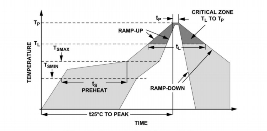
Soldering ແລະ Reflow
ສໍາລັບການເຊື່ອມໂລຫະ, ໃຊ້ຂະບວນການ reflow ທີ່ບໍ່ມີສານນໍາທີ່ແນະນໍາ: ເລັ່ງຂຶ້ນທີ່ອຸນຫະພູມບໍ່ເກີນ 3 ° C / s, ສູງສຸດປະມານ 260 ° C, ແລະຢູ່ສໍາລັບ 60-150 ວິນາທີຂ້າງເທິງ 217 ° C. ຫຼັງຈາກ reflow, ໃຫ້ກະດານເຢັນຕາມທໍາມະຊາດແລະຫຼີກເວັ້ນການເຢັນໄວ. ໂດຍປົກກະຕິແລ້ວພຽງແຕ່ຕ້ອງການຮອບວຽນການໄຫຼຄືນໜຶ່ງຄັ້ງຕໍ່ເຊັນເຊີເພື່ອຫຼີກເວັ້ນການຮ້ອນຊ້ຳໆ. ສໍາລັບ rework, ໃຊ້ທາດເຫຼັກ soldering ອຸນຫະພູມຕ່ໍາຢ່າງໄວວາເພື່ອຫຼຸດຜ່ອນເວລາຄວາມຮ້ອນ. ໃຊ້ຄວາມລະມັດລະວັງ ESD ເພື່ອປົກປ້ອງເຊັນເຊີ, ແລະກວດເບິ່ງຂໍ້ຕໍ່ເພື່ອໃຫ້ແນ່ໃຈວ່າບໍ່ມີຂໍ້ຕໍ່ເຢັນຫຼືຂົວ solder.
ການປົກປ້ອງພອດຄວາມກົດດັນ
ຫຼັງຈາກ soldering, ກວດກາແລະເຮັດຄວາມສະອາດພອດເພື່ອຮັບປະກັນບໍ່ມີ solder ຫຼື debris ຂັດຂວາງການເປີດຄວາມກົດດັນ. ຖ້າຕ້ອງການການກັນນໍ້າ, ໃຫ້ໃຊ້ຝາປິດທີ່ມີເຍື່ອລະບາຍອາກາດເພື່ອໃຫ້ຜອດເຊັນເຊີຖືກກັບບັນຍາກາດແຕ່ບໍ່ໃຫ້ນ້ໍາ. ຫຼີກເວັ້ນການປະສົມ potting ຫຼື epoxy ທີ່ຈະກວມເອົາພອດ; ແທນທີ່ຈະໃຊ້ O-rings ຫຼື gaskets ເພື່ອປະທັບຕາທີ່ຢູ່ອາໃສ, ໃຫ້ແນ່ໃຈວ່າ port ຍັງລະບາຍອາກາດ.
ການຕິດຕັ້ງແລະການປົກປ້ອງກົນຈັກ
ເຊັນເຊີຖືກຈັດໃສ່ໃນສະຖານທີ່ໂດຍແຜ່ນ solder ຂອງມັນແລະປົກກະຕິແລ້ວບໍ່ຈໍາເປັນຕ້ອງມີການສະຫນັບສະຫນູນກົນຈັກເພີ່ມເຕີມ. ຢ່າງໃດກໍຕາມ, ໃນອຸປະກອນສວມໃສ່ໄດ້, ຝາປິດຄວນສະຫນອງການປ້ອງກັນການຊ໊ອກເພື່ອທໍາລາຍຜົນກະທົບແລະການສັ່ນສະເທືອນ. ຖ້າຕ້ອງການກາວ, ໃຊ້ມັນພຽງແຕ່ອ້ອມຮອບແຄມແລະຫຼີກເວັ້ນການປົກຫຸ້ມຂອງພອດຄວາມກົດດັນຫຼືແຜ່ນ. ຢ່າຕິດເຊັນເຊີໂດຍກົງໃສ່ພື້ນຜິວທີ່ມີຄວາມຍືດຫຍຸ່ນ.
ຂັ້ນຕອນການທົດສອບແລະເຄື່ອງມື / ວິທີການແນະນໍາກ່ອນການຜະລິດຈໍານວນຫຼາຍ
Functional and Calibration Testing
ກ່ອນທີ່ຈະຜະລິດຂະຫນາດໃຫຍ່, ແນະນໍາໃຫ້ເຮັດການກວດສອບການທໍາງານແລະການທົດສອບການປັບທຽບໃນແຕ່ລະ batch ຂອງ sensors. ຂັ້ນຕອນການປົກກະຕິປະກອບມີ: 1) ການວາງເຊັນເຊີທີ່ຄວາມກົດດັນບັນຍາກາດມາດຕະຖານ (~1013 hPa) ແລະອ່ານຜົນຜະລິດເພື່ອກວດສອບການຊົດເຊີຍ; 2) ໃຊ້ແຫຼ່ງຄວາມກົດດັນຄວາມແມ່ນຍໍາຫຼືເຄື່ອງທົດສອບນ້ໍາຫນັກຕາຍເພື່ອນໍາໃຊ້ຄວາມກົດດັນໃນຫຼາຍຈຸດ (e.g., 900 hPa, 1100 hPa) ເພື່ອກວດສອບເສັ້ນຊື່ແລະຄວາມອ່ອນໄຫວ; 3) ໃຊ້ລະບົບການທົດສອບອັດຕະໂນມັດເພື່ອອ່ານຂໍ້ມູນເຊັນເຊີຜ່ານ I2C/SPI ໃນຊຸດແລະເຮັດຊ້ໍາການທົດສອບເຫຼົ່ານີ້ພາຍໃຕ້ເງື່ອນໄຂອຸນຫະພູມທີ່ແຕກຕ່າງກັນເພື່ອປະເມີນອຸນຫະພູມ drift. ນອກນັ້ນທ່ານຍັງສາມາດເຮັດການທົດສອບພາກສະຫນາມຢູ່ຈຸດລະດັບຄວາມສູງທີ່ຮູ້ຈັກ (ເຊັ່ນ: ຫໍຄອຍປັບລະດັບຄວາມສູງ) ສໍາລັບການກວດສອບຄວາມຖືກຕ້ອງຕື່ມອີກ.
ການທົດສອບດ້ານສິ່ງແວດລ້ອມແລະຄວາມຫນ້າເຊື່ອຖື
ການທົດສອບຍັງຄວນຈະປະກອບມີສິ່ງແວດລ້ອມແລະຄວາມຫນ້າເຊື່ອຖື: ເຮັດການຮອບວຽນອຸນຫະພູມໃນຫ້ອງການສະພາບອາກາດເພື່ອປະເມີນຜົນຜະລິດພຽງເລັກນ້ອຍຢູ່ໃນອຸນຫະພູມທີ່ຮ້າຍແຮງ; ເຮັດການທົດສອບຄວາມຊຸ່ມຊື່ນເພື່ອສັງເກດພຶດຕິກໍາຂອງເຊັນເຊີໃນສະພາບແວດລ້ອມທີ່ມີຄວາມຊຸ່ມຊື່ນ. ດໍາເນີນການທົດສອບການແຊ່ນ້ໍາຫຼືຄວາມກົດດັນຮອບວຽນເພື່ອກວດສອບການຜະນຶກແລະຄວາມທົນທານ, ຕົວຢ່າງໂດຍການວາງອຸປະກອນໃນຖັງນ້ໍາຫຼືຫ້ອງຄວາມກົດດັນເພື່ອຈໍາລອງການດໍານ້ໍາຊ້ໍາຊ້ອນ. ການທົດສອບການສັ່ນສະເທືອນແລະການຊ໊ອກຊ່ວຍປະເມີນຄວາມຫນ້າເຊື່ອຖືຂອງເຊັນເຊີແລະໂຄງສ້າງອຸປະກອນໂດຍລວມໃນສະພາບການເຄື່ອນໄຫວ.
ແນະນຳເຄື່ອງມື/ວິທີການທົດສອບ
ອຸປະກອນການທົດສອບທີ່ແນະນໍາແລະວິທີການປະກອບມີ:
ເຄື່ອງປັບຄວາມດັນທີ່ຊັດເຈນ: ຕົວຢ່າງ. Fluke 716 ຫຼື Mensor CPC100, ເພື່ອສະຫນອງຄວາມກົດດັນທາງອາກາດຫຼືນ້ໍາທີ່ມີໂຄງການ.
ຫ້ອງລະບາຍຄວາມຮ້ອນ/ຄວາມຊຸ່ມຊື່ນ: ເພື່ອທົດສອບຜົນກະທົບຂອງອຸນຫະພູມແລະຄວາມຊຸ່ມຊື່ນໃນເຊັນເຊີ.
ກະດານທົດສອບອັດຕະໂນມັດ: ດ້ວຍ MCU ຫຼື FPGA ເພື່ອ batch ອ່ານ/ຂຽນເຊັນເຊີລົງທະບຽນຜ່ານ I2C/SPI ແລະບັນທຶກຂໍ້ມູນ.
ການຕິດຕັ້ງການທົດສອບຄວາມກົດດັນນ້ໍາ: ຖັງນ້ໍາຄວາມກົດດັນຫຼືຫ້ອງຄວາມກົດດັນເພື່ອຈໍາລອງຄວາມເລິກຂອງການດໍານ້ໍາທີ່ແຕກຕ່າງກັນ.
ເຄື່ອງວິເຄາະພະລັງງານ ຫຼື oscilloscope: ເພື່ອຕິດຕາມເວລາການເກັບຕົວຢ່າງຂອງເຊັນເຊີ ແລະການແຕ້ມປະຈຸບັນ.
ມາດຕະຖານອ້າງອີງ: ໃຊ້ເຊັນເຊີຄວາມດັນມາດຕະຖານທີ່ປັບທຽບເພື່ອກວດສອບຜົນການວັດແທກ.
ຂັ້ນຕອນການປ່ຽນໂໝດ ແລະປັດໄຈການຊົດເຊີຍສິ່ງແວດລ້ອມ
Trigger ສໍາລັບການປ່ຽນໂໝດ
ທ່ານຕ້ອງກໍານົດເວລາທີ່ຈະປ່ຽນຈາກໂຫມດລະດັບຄວາມສູງໄປຫາໂຫມດດໍານ້ໍາ. ຍຸດທະສາດທີ່ງ່າຍດາຍຄືການປະກາດການດໍານ້ໍາໃນເວລາທີ່ອຸປະກອນກວດພົບຄວາມກົດດັນທີ່ເພີ່ມຂຶ້ນຢ່າງໄວວາເກີນຂອບເຂດຂອງບັນຍາກາດປົກກະຕິ (ຕົວຢ່າງເຊັ່ນ, ຢູ່ທີ່ສູງກວ່າ 1100 hPa). ເພື່ອຫຼີກເວັ້ນການກະຕຸ້ນທີ່ບໍ່ຖືກຕ້ອງ, ທ່ານສາມາດຮຽກຮ້ອງໃຫ້ມີຄວາມກົດດັນເກີນຂອບເຂດສໍາລັບເວລາທີ່ຍືນຍົງຫຼືໃຊ້ເຊັນເຊີຄວາມຊຸ່ມຊື່ນຫຼືກົນໄກການກວດພົບນ້ໍາອື່ນໆ. ສ່ວນຕິດຕໍ່ຜູ້ໃຊ້ຍັງສາມາດສະເໜີການສະຫຼັບໂໝດຄູ່ມືເປັນການສໍາຮອງໄດ້ ຖ້າການກວດຫາອັດຕະໂນມັດລົ້ມເຫລວ.
ສູດການຄິດໄລ່ລະດັບຄວາມສູງ
ໃນໂຫມດລະດັບຄວາມສູງ, ໃຊ້ສູດບາໂຣເມຕຣິກເພື່ອປ່ຽນຄວາມກົດດັນເປັນລະດັບຄວາມສູງ. ສູດທົ່ວໄປແມ່ນ h ≈ 44330 × (1 − (P/Po)^0.1903), ບ່ອນທີ່ Po ແມ່ນຄວາມກົດດັນອ້າງອີງລະດັບທະເລ. ໃນທາງປະຕິບັດ, ໃຊ້ຄວາມກົດດັນອ້າງອີງທີ່ວັດແທກໃນຕອນເລີ່ມຕົ້ນ (ຫຼືສະຫນອງໃຫ້ໂດຍຂໍ້ມູນລະດັບຄວາມສູງ GPS) ເປັນ Po, ແລະນໍາໃຊ້ການອ່ານອຸນຫະພູມຂອງເຊັນເຊີສໍາລັບການຊົດເຊີຍ. ທ່ານສາມາດນໍາໃຊ້ການເຄື່ອນຍ້າຍສະເລ່ຍຫຼື Kalman filter ເພື່ອກ້ຽງຜົນຜະລິດແລະຫຼຸດຜ່ອນສິ່ງລົບກວນ.
ສູດການຄິດໄລ່ການດໍານ້ໍາ
ໃນໂໝດດຳນ້ຳ, ໃຫ້ຄຳນວນຄວາມເລິກຈາກຄວາມດັນ hydrostatic: D ≈ (P − P0)/(ρ·g). ທີ່ນີ້ P0 ແມ່ນຄວາມກົດດັນຂອງບັນຍາກາດຢູ່ດ້ານ, ເຊິ່ງສາມາດບັນທຶກໃນຕອນເລີ່ມຕົ້ນຂອງການດໍານ້ໍາ. ຄວາມຫນາແຫນ້ນρຂອງນ້ໍາຈືດແມ່ນປະມານ 1000 kg / m³ (ສູງກວ່າເລັກນ້ອຍສໍາລັບນ້ໍາທະເລ), ແລະອຸນຫະພູມຜົນກະທົບຕໍ່ຄວາມຫນາແຫນ້ນເຊັ່ນດຽວກັນ. ກົດລະບຽບທີ່ງ່າຍດາຍແມ່ນວ່າທຸກໆ 100 hPa ເທົ່າກັບປະມານ 1 ແມັດຂອງຄວາມເລິກຂອງນ້ໍາຈືດ. ລະບົບຄວນສືບຕໍ່ວັດແທກຄວາມກົດດັນແລະປັບປຸງຄວາມເລິກໃນເວລາທີ່ແທ້ຈິງ.
ປັດໄຈການຊົດເຊີຍສິ່ງແວດລ້ອມ
ເພື່ອປັບປຸງຄວາມຖືກຕ້ອງ, ຊົດເຊີຍປັດໃຈສິ່ງແວດລ້ອມ. ການອ່ານອຸນຫະພູມໃນຕົວຂອງເຊັນເຊີສາມາດແກ້ໄຂການເລື່ອນຄວາມກົດດັນເນື່ອງຈາກການປ່ຽນແປງຂອງອຸນຫະພູມ. ໃນຮູບແບບລະດັບຄວາມສູງ, ທ່ານອາດຈະພິຈາລະນາຜົນກະທົບຂອງຄວາມຊຸ່ມຊື່ນຕໍ່ຄວາມຫນາແຫນ້ນຂອງອາກາດ. ໃນຮູບແບບການດໍານ້ໍາ, ບັນຊີສໍາລັບຜົນກະທົບຂອງອຸນຫະພູມນ້ໍາແລະຄວາມເຄັມຕໍ່ຄວາມຫນາແຫນ້ນ (ຕົວຢ່າງ, ຄວາມຫນາແຫນ້ນຂອງນ້ໍາທະເລແມ່ນສູງກວ່ານ້ໍາຈືດເລັກນ້ອຍ). ນອກຈາກນັ້ນ, ການໃຊ້ຕົວກອງຕ່ໍາຜ່ານຫຼືສະເລ່ຍຕໍ່ຂໍ້ມູນຄວາມກົດດັນສາມາດເອົາສິ່ງລົບກວນໃນໄລຍະສັ້ນແລະສະຖຽນລະພາບຜົນໄດ້ຮັບ.
ສະຫຼຸບ
ການນໍາໃຊ້ເຊັນເຊີຄວາມກົດດັນຢ່າງແທ້ຈິງ MEMS ເພື່ອວັດແທກຄວາມສູງແລະຄວາມເລິກຂອງການດໍານ້ໍາໃນຫນຶ່ງອຸປະກອນຮຽກຮ້ອງໃຫ້ມີການແກ້ໄຂລະດັບຄວາມກົດດັນທີ່ແຕກຕ່າງກັນ, ຄວາມຕ້ອງການຄວາມຖືກຕ້ອງ, ແລະສູດການຄິດໄລ່ສໍາລັບແຕ່ລະໂຫມດ. WF282A, ດ້ວຍຄວາມຖືກຕ້ອງສູງ, ພະລັງງານຕໍ່າ, ຊຸດກະທັດຮັດ, ແລະ FIFO ທີ່ມີໃນຕົວ, ສະຫນອງພື້ນຖານຮາດແວທີ່ເຂັ້ມແຂງສໍາລັບການວັດແທກສອງໂຫມດ. ໃນການອອກແບບ, ຕ້ອງເອົາໃຈໃສ່ກັບຮູບແບບ PCB ແລະການເຊື່ອມໂລຫະ, ການຮັກສາພອດຄວາມກົດດັນທີ່ຊັດເຈນ, ແລະການທົດສອບແລະການປັບຕົວຢ່າງລະອຽດ. ໂດຍການໃຊ້ການຊົດເຊີຍສິ່ງແວດລ້ອມທີ່ຖືກຕ້ອງ (ເຊັ່ນ: ສໍາລັບອຸນຫະພູມແລະຄວາມຫນາແຫນ້ນ), ອຸປະກອນສາມາດສະຫຼັບລະຫວ່າງລະດັບຄວາມສູງແລະການດໍານ້ໍາແບບ seamlessly ແລະບັນລຸການວັດແທກທີ່ຊັດເຈນ.
ການແນະນໍາຂ້າງເທິງພຽງແຕ່ scratches ດ້ານຂອງຄໍາຮ້ອງສະຫມັກຂອງເຕັກໂນໂລຊີເຊັນເຊີຄວາມກົດດັນ. ພວກເຮົາຈະສືບຕໍ່ຄົ້ນຫາປະເພດຕ່າງໆຂອງອົງປະກອບເຊັນເຊີທີ່ໃຊ້ໃນຜະລິດຕະພັນຕ່າງໆ, ວິທີການເຮັດວຽກ, ແລະຂໍ້ດີແລະຂໍ້ເສຍຂອງມັນ. ຖ້າທ່ານຕ້ອງການລາຍລະອຽດເພີ່ມເຕີມກ່ຽວກັບສິ່ງທີ່ໄດ້ສົນທະນາຢູ່ທີ່ນີ້, ທ່ານສາມາດກວດເບິ່ງເນື້ອຫາທີ່ກ່ຽວຂ້ອງໃນພາຍຫຼັງໃນຄູ່ມືນີ້. ຖ້າຫາກວ່າທ່ານກໍາລັງກົດດັນສໍາລັບການໃຊ້ເວລາ, ທ່ານຍັງສາມາດຄລິກທີ່ນີ້ເພື່ອດາວໂຫລດລາຍລະອຽດຂອງຄູ່ມືນີ້ ຂໍ້ມູນ PDF ຜະລິດຕະພັນ PDOR Air.
ສໍາລັບຂໍ້ມູນເພີ່ມເຕີມກ່ຽວກັບເຕັກໂນໂລຊີເຊັນເຊີອື່ນໆ, ກະລຸນາ ເຂົ້າເບິ່ງຫນ້າສັນຍາລັກຂອງພວກເຮົາ.