- За WFсенсори
Packaging directly affects the function, stability and cost of MEMS Air pressure sensors. Early packages were metal, hermetic enclosures to protect fragile chips; as passivation and fabrication improved, packaging took on more roles — electrical connections, mechanical interfaces, fluid path control and thermal management. In manufacturing costs, design, wafer fabrication and packaging/testing typically each take roughly a third, so packaging choices have a big say in competitiveness. This guide considers common package forms (leadframe, SMD, LCC) and core process steps (tape-mount, dicing, die attach, wire bonding, molding, plating, marking, trim/form) to provide practical advice that balances reliability and manufacturability.
Каталог
1. Packaging basics and design considerations
When you design a package, you must balance hermeticity, mechanical strength, electrical connection and fluid-port layout. The package holds both the MEMS die and the ASIC sensor chip and must reliably transmit pressure through whichever port design you choose. For differential or absolute-pressure use, a dual-port layout or a single-port with reference cavity will shape the package geometry and tube fittings. Think manufacturability early: leadframe pin pitch affects pick-and-place and test fixturing; port diameter and flange location influence assembly robustness. Sealing can be soft gaskets, epoxy potting or local glass/ceramic seals — each trades cost against long-term stability. Design choices up front show up later in dicing, die attach and bonding yields, so early decisions affect throughput and consistency.
Hermetic sealing and environmental protection
Designing for hermeticity means choosing port openings and sealing approaches that stand up to humidity and chemical exposure. Hermetic doesn’t always mean totally sealed — some designs deliberately include vents or filter membranes to balance response speed against long-term drift. Seal behaviour ties to enclosure material: metal, ceramic or high-performance plastics have different thermal expansion coefficients and so affect stress at interfaces.
Leadframes and package types
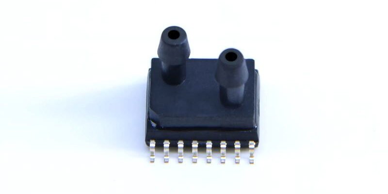
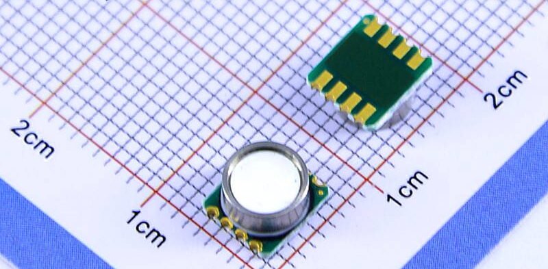
Package style dictates pin layout, assembly approach and test access. Leadframes suit high-volume runs and help thermal dissipation, while LCC and SMD packages make automated surface-mount assembly easier. Leave room in the package for wire bonds and for molding with EMC; build stress-relief features around port areas so mechanical loads do not transmit to the sensing membrane.

2. Typical packaging process flow
A typical flow covers wafer fixation (tape mount), dicing, inspection, die attach, oven cure, wire bonding, molding, mold cure, plating, marking and trim/form. Specific sequences and equipment may vary, but these are the core steps from die to shippable part. Each stage affects final performance: dicing quality determines die damage rates; die-attach bondline thickness alters thermal and mechanical coupling; bonding quality governs electrical stability and high-temperature behaviour. Strict control of environment, materials and lot traceability on the production line is essential to keep batch-to-batch consistency.
Tape-mount and dicing processes
Tape-mount and ring fixturing prevent wafer cracking during dicing. Dicing uses diamond blades along the streets, typically cutting to about 95% of wafer thickness before separation. Blade wear, cut speed and coolant strategy influence die stress and edge chipping. Post-dice optical inspection with high magnification weeds out obviously damaged dies and reduces downstream rejects.
Die attach and wire bonding
Die attach secures the die to the leadframe or substrate using epoxy or solder; glue thickness and placement affect mechanical coupling. After placement, an oven cure step hardens the adhesive. Wire bonding then uses high-purity gold or aluminium wire to connect die pads to package leads; plasma cleaning precedes bonding to remove contaminants. Bonding parameters — power, force and time — must be optimised to prevent pad lift or weak bonds.
3. Assembly and mechanical interface techniques
Assembly mounts the packaged device to the fluid system or PCB. Pressure-port design matters most at this stage: port geometry, gasket material and flange fit determine leak rate and response time. For different applications you might use small push-fit tubes, glued joints, or an open port with a membrane filter. In volume assembly, aim for automation: fixtures for clamping, fluid connection and soldering should minimise stress transfer so the membrane remains unstressed and correctly aligned.
Pressure-port structural design
Control axial and radial tolerances at the pressure ports — they’re critical. Internal cavity volume affects response time and drift. For high-repeatability sensors, minimise dead volume and consider flow-guiding features to avoid pockets. Seals can be micro O-rings or epoxy, chosen for compatibility with moisture, oil or other target media.
Enclosure and mechanical-strength matching
Material choice and wall thickness set shock and thermal-cycle resistance. Balance stiffness with stress relief: ribs or flexible transitions around the port area reduce load transfer to the sensing membrane. Place PCB mounting and clamp points away from the membrane and avoid matching structural resonances that could worsen long-term drift.
4. Packaging materials, curing and reliability validation
Choosing the right EMC, adhesives and plating finishes is key to long-term stability. EMC should be stored cold and dry to prevent moisture uptake; after molding, a mold-cure accelerates polymer crosslinking to improve mechanical strength. Plating protects leads from corrosion, typically nickel or gold finishes. Reliability validation spans thermal shock, damp heat, vibration and salt spray; test outcomes feed back into material selection and process tweaks to meet target lifetimes.
Packaging material selection and storage
Evaluate adhesives and encapsulants for cure profile, moisture uptake and CTE match. Storage conditions before use matter: hydrated materials can cause moulding defects or internal stress, so keep hygroscopic materials in low-temperature, dry storage with batch traceability.
Lifetime and reliability validation
Run temperature cycling, damp-heat, mechanical shock and electrical ageing tests. These checks verify hermeticity, lead integrity and port seal lifetime, and monitor membrane drift. Use results to refine design and materials in a closed loop of continuous improvement.
5. System integration with ASIC sensor chips
Modern MEMS Air pressure sensors often come integrated with an ASIC sensor chip for signal conditioning, power management and temperature compensation. Packaging must provide the ASIC with heat paths and a stable ground, while preventing digital noise coupling through leads or structure to the MEMS membrane. Integration methods include flip-chip on a common substrate or hybrid packages to shorten signal paths and improve immunity. Calibration is typically done after packaging to compensate for stress and environmental offsets introduced by the package.
Hybrid packaging and system integration
Hybrid packages colocate MEMS and ASIC inside one module, using wire bonds or flip-chip to trim interconnect length. Layout must manage thermal coupling and EMC, and leave test/programming pads for calibration or final parameter programming on the production line.
Calibration and test strategies
Calibration ensures shipped units meet specs — perform static and dynamic checks on pressure/temperature rigs to record zero, sensitivity, linearity and hysteresis. Store calibration constants in the ASIC’s non-volatile memory or apply compensation in firmware. On the production line, combine lot sampling with full testing where needed to balance throughput and final quality.
Висновок
Packaging is both physical protection and a key factor for manufacturability and market success. By including assembly feasibility in design, controlling tape-mount, dicing, die attach and bonding parameters, and choosing materials for long-term reliability, teams can protect performance while improving yield. Production controls should cover material lot management, equipment maintenance, statistical process control, and clear marking/traceability. Final functional tests and calibration ensure each shipment meets spec, reducing returns and preserving brand reputation.
Наведене вище введення лише дряпає поверхню застосування технології датчиків тиску. Ми продовжимо досліджувати різні типи сенсорних елементів, які використовуються в різних продуктах, як вони працюють, а також їхні переваги та недоліки. Якщо вам потрібна додаткова інформація про те, що тут обговорюється, ви можете переглянути відповідний вміст далі в цьому посібнику. Якщо у вас немає часу, ви також можете клацнути тут, щоб завантажити докладну інформацію про ці посібники Дані датчика тиску повітря PDF.
Для отримання додаткової інформації про інші сенсорні технології, будь ласка Відвідайте нашу сторінку датчиків.