- За WFсенсори
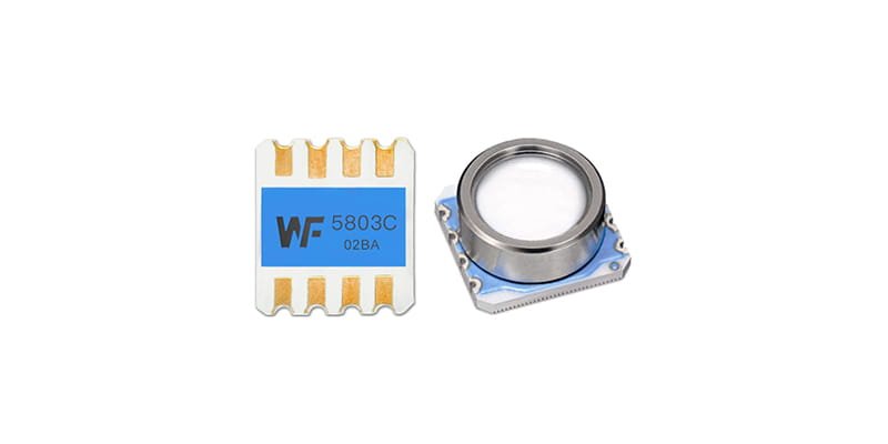
At ground level, standard atmospheric pressure is roughly 100 kPa and falls with altitude. With a high-precision sensor you can convert pressure into altitude. A moving platform adds dynamic pressure from its speed; by pairing a total-pressure sample with a static-pressure sample that only reflects ambient pressure, you can derive both altitude and speed. A UAV atmospheric measurement system normally comprises a front-end pressure probe, differential pressure plumbing and a processing unit. The pictured part is suitable as a front-end sampling point: the metal port is good for capturing direct flow, and the four-pad layout is convenient for SMD mounting and electrical connections. However, installation orientation and enclosure shielding need careful attention to reduce flow interference and thermal drift.
Каталог
1. Sensor placement & interfaces
On small aircraft, stable pressure measurement starts with placing the sensor where it truly represents outside air, while avoiding local turbulence and nearby heat sources. Common practice is to put the pressure port at the nose or on a streamlined surface: a total-pressure (pitot-like) intake facing the flight direction, and a static-pressure port on a surface perpendicular to the flow. For high-dynamic, high-speed platforms, the probe should be as far forward as feasible to get a cleaner dynamic-pressure signal. On tiny drones, though, mechanical fixing and low-profile enclosures must also handle vibration and sealing. The package pictured — a metal pressure port with four solder pads — lends itself to SMD mounting, but you should design micro-tubing or pressure traces to prevent wind erosion and icing. Keep the electrical interface close to filtering and amplification stages to minimise wiring-induced noise, and pay attention to ground treatment so the pressure port’s electrical environment is stable.
sensor mounting location
When choosing a mounting spot, aim for a point that gives representative pressure. Exposed points near the nose, fuselage front or wing leading edge are commonly used for total-pressure sampling; static ports should be placed on a surface that sees steady flow and sits perpendicular to the flight vector. Avoid placing ports in control-surface wakes, propwash, or close to large heat sources. Mechanically, secure the sensor to resist vibration while preserving sealing; using low thermal-expansion materials and flexible mounts can reduce stress-induced offsets.
airflow effects & mounting angle
Mounting angle affects how effectively you capture dynamic pressure and how immune the static port is to disturbances. Small misalignments can introduce extra error into total-pressure readings, so align the probe with the expected angle of attack and validate in wind-tunnel tests or CFD. On multirotors, downwash has a strong effect on side static ports; record pressure deviations across flight regimes and build correction tables or use real-time filtering to compensate for transient disturbances.

2. Data computation & signal chain
To compute altitude and speed you need both hardware and software to be up to the job. Typically the backend uses two pressure channels: one absolute-pressure channel for altitude, and a differential channel (total minus static) for speed. The relationship between differential pressure and speed comes from fluid mechanics and is usually expressed in a straightforward mapping. In practice the focus isn’t on exotic formulas but on making sure the sensor works in its linear range, has low noise floor, and the sampling bandwidth meets dynamic requirements. The analogue front end should include anti-alias filtering, differential amplification and temperature compensation; the digital side should handle denoising, time alignment and attitude-coupling corrections. Crucially, set the sampling rate to exceed at least twice the highest dynamics you expect, and consider adaptive filtering to balance transient response and steady-state precision.
hardware filtering & sampling rate
Analogue filtering should remove high-frequency noise before the ADC. A common approach is a second-order low-pass filter combined with a differential amplifier. Sample rate depends on the vehicle’s motion bandwidth — multirotors often have lower vertical-bandwidth requirements than high-speed fixed-wing aircraft, which need much higher rates. ADC resolution and sensor sensitivity together determine the smallest pressure change you can resolve; pick components so quantisation noise doesn’t dominate.
formulas & computation flow
The computation steps typically start with temperature and zero offset compensation, then convert absolute pressure to altitude. Differential pressure gives dynamic pressure; applying the relevant fluid-dynamics relation yields speed. Be mindful that aircraft attitude (pitch/roll) can add components to measured pressures; fuse pressure data with attitude sensors to transform measurements into a consistent reference frame and ensure physically meaningful altitude and speed outputs.
3. Calibration & error control
Sensor accuracy largely dictates the trustworthiness of derived flight parameters. Calibration has two parts: factory characterisation and platform-level calibration after installation. Factory data provide sensitivity and linearity; platform calibration captures installation-specific errors through static and dynamic tests and produces compensation coefficients. Typical error sources are temperature drift, zero drift, mechanical stress and pressure-path leakage. For dynamic errors, use ground rigs and short flight tests to derive speed-related corrections; for static bias, verify zero against a known pressure reference or using known-altitude checkpoints. Over time, implement self-check routines and telemetry so you can spot drift.
zero and thermal drift handling
Zero drift often stems from temperature swings or mechanical stress. Use a temperature sensor to log ambient and mount temperature and apply real-time thermal compensation curves in software. Keep an updatable zero-offset table that can be refreshed during ground checks. Hardware choices like low-thermal-drift materials and compact thermal paths also help reduce drift.
environmental & dynamic error sources
Wind shear, airframe vibration, icing and contamination can all skew readings. On multirotors, downwash and prop wash heavily affect nearby static ports, so their position matters. On high-speed platforms local compressibility effects or shocks can add errors; quantify these with simulation and testing and encode compensations in the system.
4. System integration & reliability verification
Integrating pressure data into flight control and navigation requires robust signal availability and redundancy. Integration covers electrical interfaces, data protocols, attitude coupling and fault detection logic. Real-time use means you must size communication bandwidth and processing delays correctly and define failure modes so erroneous pressure data don’t drive unsafe control decisions. Validation includes bench testing, ground calibration and staged flight tests: after installation do low-altitude flights and cross-check against GNSS height and ground references, then exercise different weather and flight conditions to test robustness. For mission-critical platforms, consider dual or multiple pressure inputs and consistency checks.
software redundancy & signal checking
At software level, fuse pressure channels with GNSS and inertial sensors using filtering techniques (Kalman filters are common) to weight inputs appropriately. Implement anomaly detection to spot transients, drifts or disconnections; on detection the system should fall back to alternate sensors or estimation modes to keep the vehicle safe.
flight-test validation flow
Use a staged process: start with static calibration and baseline logging; then perform short, low-speed, low-altitude flights to compare pressure-derived altitude with known references; finally, run mission-profile flights. After each sortie, replay pressure, attitude and GNSS logs, analyse residuals and adjust corrections until performance meets specs.
5. Practical advice & component selection
When choosing sensors, balance measurement range, sensitivity, thermal drift, package and interface. Small UAVs often favour compact, fast-response devices with integrated ports; high-speed platforms prioritise range and dynamic linearity. Pick parts with proven long-term stability and repeatability, and that are easy to swap in the field. The pictured component’s metal port suits direct exposure but needs micro-tubing or pressure traces to reduce contamination risk. Also factor in ingress protection, dust and moisture resistance, and operating temperature range to ensure dependable performance in mission conditions.
recommended sensor types & interfaces
Use an absolute-pressure sensor as the altitude reference and a differential-pressure channel for speed. Devices should offer either a clean digital output or a low-noise analogue signal for easier integration. For tasks with fast dynamics, choose sensors with high-speed outputs and onboard temperature compensation to reduce external correction complexity.
maintenance & long-term stability
Regularly check seals, pressure pathways and electrical connections. Track long-term drift with ground checks and flight-log analysis and replace or recalibrate sensors when drift exceeds limits. Modular design helps with quick field swaps and reduces downtime.
Висновок
With the right sensor choice, careful mechanical layout, rigorous signal processing and a thorough calibration regime, you can reliably measure altitude and speed on a UAV. Use absolute pressure as the altitude baseline, derive speed from total-minus-static pressure, and fuse these with attitude and GNSS data to boost overall measurement confidence. The small SMD device pictured is suitable for front-end sampling on compact platforms, but installation, pressure traces and thermal management must be handled properly. For engineers, the key is to identify error sources and mitigate them through design and validation so you turn raw pressure readings into trustworthy flight parameters.
Наведене вище введення лише дряпає поверхню застосування технології датчиків тиску. Ми продовжимо досліджувати різні типи сенсорних елементів, які використовуються в різних продуктах, як вони працюють, а також їхні переваги та недоліки. Якщо вам потрібна додаткова інформація про те, що тут обговорюється, ви можете переглянути відповідний вміст далі в цьому посібнику. Якщо у вас немає часу, ви також можете клацнути тут, щоб завантажити докладну інформацію про ці посібники Дані датчика тиску повітря PDF.
Для отримання додаткової інформації про інші сенсорні технології, будь ласка Відвідайте нашу сторінку датчиків.