Katalog

Modern sensor technology has advanced rapidly. When replacing old pressure and temperature sensors, engineers must consider multiple factors. This article focuses on real-world scenarios and customer concerns to highlight key points for making informed decisions. Topics include understanding legacy system requirements, comparing analog vs digital sensor options, installation and soldering considerations, pre-production testing, and maintenance strategies to ensure long-term system stability.
1. Understand Legacy System Requirements
1.1 Measurement Range and Accuracy
Before replacing sensors, clearly define the original system’s pressure and temperature measurement range. Note the working pressure and temperature limits and the required accuracy. The new sensor should cover at least the same range and provide equal or better precision. Also verify if the control system requires calibrated or scaled outputs. A mismatched range or insufficient precision could degrade system performance.
1.2 Environmental Conditions and Reliability
Consider the environment in which the old sensor operated. Was it exposed to extreme temperatures, high humidity, corrosive chemicals, or strong vibrations? The replacement must tolerate the same conditions. For example, it may need a specific IP rating, corrosion-resistant materials, or vibration tolerance. Plan any extra protection (like coatings or shields) so the new sensor remains reliable in harsh conditions.
1.3 Interfaces and Compatibility
Analyze the electrical and mechanical interfaces of the legacy sensor to ensure compatibility. Electrically, determine if the old sensor used an analog output (0–5V, 4–20mA) or a digital communication protocol (I2C, SPI, UART, etc.). If the new sensor outputs a different signal, you may need interface modules or signal conditioning. Mechanically, verify the mounting style, pressure port size, and connector type. Different packaging or pinouts might require redesigning the mounting bracket or piping. If the system requires fail-safe operation, ensure the new sensor provides error signals (for example, a specific output when the sensor is open-circuit or short-circuit).
2. Choose the Right Sensor Technology
2.1 Analog vs Digital Sensors
Analog Sensors output a voltage or current signal (e.g., 0–5V or 1–5.5uA). They have a simple interface and can be reliable, but the signal is prone to noise and drift. Analog signals usually require external amplifiers and filters for precision.
Digital Sensors include an ADC and output data over I2C, SPI, UART, or other digital interfaces. They provide stable, noise-resistant communication and often include built-in calibration, improving accuracy. Before choosing, ensure your controller supports the sensor’s protocol.
When selecting, consider the system’s ability to handle each signal type, the calibration process, and cost implications.
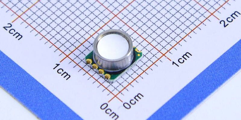
2.2 Benefits of MEMS Sensors
Modern MEMS (Micro-Electro-Mechanical) pressure sensors are compact and consume very low power. They often integrate temperature compensation and signal conditioning on-chip. Compared to older strain-gauge sensors, MEMS devices typically respond faster and maintain stability over temperature changes. They also offer good batch-to-batch consistency, which is ideal for large production volumes. However, evaluate the chosen MEMS sensor’s long-term stability and drift, as every device can age differently.
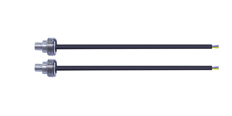
2.3 Packaging and Interface Types
The sensor’s package affects how it can be mounted and connected. Common packages include metal cans or plastic bodies with pressure ports, and internal pin layouts vary (through-hole vs. surface-mount). Digital sensor packages (like LGA or QFN) usually have minimal pins and are soldered directly, while analog sensors might use dual-inline or multi-pin formats requiring wired connections. Also check the communication interface: analog voltage/current, I2C, SPI, or UART. Ensure your circuit design matches the sensor’s package and pinout.
3. Installation and Soldering Considerations
3.1 Packages and Soldering

Sensor package type directly affects how it is soldered or mounted. For example, through-hole (DIP) devices use pins that go through the board and can be wave-soldered or hand-soldered. Surface-mount packages (like SMD) are designed for reflow soldering. Choose a package compatible with your assembly process and PCB layout. Ensure you follow the manufacturer’s recommended soldering profile to avoid overheating. After soldering, analog sensors may need a recalibration step to account for any shifts caused by heating.
3.2 PCB Layout and Routing
Layout the PCB with signal quality in mind. Place the sensor close to its signal conditioning or ADC to minimize trace length. For analog sensors, give them a dedicated ground plane and keep them away from high-power or noisy components. Add bypass capacitors near the sensor pins to filter noise. If the sensor is digital, make sure I2C/SPI traces have proper termination or pull-ups as needed.
3.3 Sealing and Environment Protection
Make sure the sensor enclosure and pressure port are sealed against the environment. In wet or dirty conditions, use sealant or O-rings on the port to block moisture and debris. In corrosive atmospheres, consider a protective coating or housing. Check that any tubing or fittings are tight to prevent leaks. Inspect seals and filters regularly in maintenance to prevent drift from contaminants.
3.4 ESD and Thermal Stress
Sensors have sensitive internal electronics. Use ESD precautions (like wrist straps and anti-static bags) during handling and assembly. Avoid exposing the sensor to rapid temperature swings or extreme heat during operation. If the sensor will see repeated thermal cycling, consider slow warm-up/cool-down processes or thermal buffers to reduce stress on the device.
4. Testing and Measurement Before Mass Production
4.1 Prototype Testing and Calibration
Early in development, test the replacement sensor’s performance. Use calibrated pressure sources and temperature baths to measure its response. Check key parameters like sensitivity, linearity, and hysteresis. Use the results to calculate calibration factors so the sensor output matches actual pressure/temperature. Document these calibration values; they will be used in production to ensure each sensor is calibrated consistently.
4.2 Environmental Stress Testing
Before full production, simulate real-world stress on the sensor. Perform temperature cycling, thermal shock, humidity exposure, and vibration tests. These stress tests reveal issues like drift, offset shifts, or mechanical failures. For example, cycling the sensor between high and low temperatures can show if its output changes with aging. Address any failures by improving the design or choosing a more robust sensor model.
4.3 Production Testing and Quality Control
For mass production, set up a testing process to verify each sensor. Automated test fixtures can apply known pressures and record outputs to confirm accuracy. Test at least the zero and full-scale outputs on every unit, or use statistical sampling if time is limited. Monitor yield rates and parameter distributions. If results deviate, adjust manufacturing processes or retrain operators. Keep records of test data to track long-term quality trends.
4.4 Traceability and Documentation
Keep detailed records of calibration and test data for each production batch. Assign batch or serial numbers to sensors and store their performance logs. This traceability makes it easier to identify and address issues later. Good documentation also helps with regulatory compliance and improves customer confidence in the quality and consistency of the product.
5. Maintenance Strategies for Long-Term Stability
5.1 Regular Calibration and Servicing
Sensors can drift over time. Establish a maintenance schedule to recalibrate sensors periodically. The frequency depends on how critical the measurement is and the operating environment. During calibration, follow the same procedure used in development to ensure accuracy. When replacing worn sensors, use the same model or a validated equivalent, and update calibration settings accordingly.
5.2 Performance Monitoring and Diagnostics
Continuously monitor sensor output against expected values. Set alarm thresholds for deviations that indicate potential failure. If a sensor’s readings suddenly change or become noisy, inspect the sensor and wiring immediately. Maintenance teams should be aware of common failure modes (such as clogging of pressure ports, corrosion, or wiring faults) to troubleshoot quickly.
5.3 Environmental Management
Keep sensors and surroundings clean to extend life. Prevent dust, dirt, oil, or other contaminants from blocking the pressure port or sensor housing. In harsh environments, use protective covers or filters and clean sensors regularly. Control ambient temperature and humidity when possible, and provide insulation or cooling to mitigate extreme conditions affecting accuracy.
5.4 Spare Parts and Upgrades
Maintain an inventory of spare sensors to minimize downtime. Choose sensors with long-term supplier support, or find drop-in replacements if original models are discontinued. Periodically review new sensor technologies—upgrading to newer, more stable sensors can improve system performance. Always test any new sensor in your system before full deployment.
Çözüm
When replacing old pressure and temperature sensors, start by thoroughly understanding the original system’s requirements. Choose a new sensor that meets or exceeds those specifications, considering analog vs digital output, packaging, and cost. Follow proper installation and soldering practices (including PCB layout and sealing) to ensure reliable operation. Perform comprehensive testing—from prototype calibration to environmental stress tests—to validate the replacement under real conditions. Finally, implement regular calibration, monitoring, and keep spare sensors on hand as part of your maintenance strategy to ensure reliable operation and long-term system stability.
Yukarıdaki giriş, basınç sensörü teknolojisi uygulamalarının yalnızca yüzeyini çizmektedir. Çeşitli ürünlerde kullanılan farklı sensör elemanları türlerini, bunların nasıl çalıştığını, avantajlarını ve dezavantajlarını keşfetmeye devam edeceğiz. Burada tartışılanlar hakkında daha fazla ayrıntı istiyorsanız bu kılavuzun ilerleyen bölümlerindeki ilgili içeriğe göz atabilirsiniz. Eğer vaktiniz kısıtlıysa bu kılavuzun detaylarını indirmek için buraya da tıklayabilirsiniz. Hava Basınç Sensörü Ürünü PDF verileri.
Diğer sensör teknolojileri hakkında daha fazla bilgi için lütfen Sensörler sayfamızı ziyaret edin.
Information is based on publicly available reliable sources such as Wikipedia: Basınç ölçümü, Replacing Old Pressure and Temperature Sensors Recommend