A differential pressure sensor assesses filter clogging by measuring the pressure difference between upstream and downstream. Upstream is the high side (connected to the sensor’s high-pressure port), downstream is the low side (connected to the low-pressure port). When the filter is clean, the differential pressure is roughly zero; it rises as the filter clogs. Picking the right gas-flow pressure sensor and differential pressure sensor, and pairing them with proper calibration and signal conditioning, gives you real-time visibility into equipment status and lets the system act automatically.
แคตตาล็อก
1. Differential pressure measurement principle and sensor installation
1.1 Definition of differential pressure and measurement points
Differential pressure is the pressure difference between two points in a pipeline: upstream (A), before the filter, which is the high side; downstream (C), after the filter, which is the low side. The filter removes particles or contaminants driven by upstream pressure; when it’s clean the differential is about zero, and as it clogs the downstream pressure drops and the differential rises roughly linearly. A differential pressure sensor converts that difference into a linear electrical signal, which serves as a live indicator for filter monitoring pressure sensors to detect resistance changes and trigger maintenance or alarms.
1.2 Tubing and dual-port connection tips
When you install it, connect the high-side tubing to the inlet line and the low-side tubing to the outlet. A dual-port design makes the measurement point clear and simplifies reference checks. Keep tubing short and avoid sharp bends to reduce dynamic lag and the chance of liquid traps. For gas systems, sealing, bend angles, and vibration isolation are also critical—proper installation cuts down on tubing-induced errors so the filter-monitoring pressure sensor gives steadier, more reliable output.

2. Calibration & signal mapping
2.1 Two-point calibration method and example (100 PSI / 20 PSI)
Typical calibration example: the system uses a pump with a filter and 100 PSI line pressure. When downstream pressure drops to 80 PSI the filter should be replaced—that’s a 20 PSI differential. If the sensor runs on 24 VDC and outputs 4–20 mA, it will read 4 mA with a clean filter and ramp up to 20 mA at 20 PSI differential. Calibrate with known pressure references using two-point calibration so the linear mapping across the range matches the alarm thresholds the controller uses.
2.2 mV signal chain and amplification/conditioning
mV-level differential sensors put out very small signals, so you need front-end amplification, filtering and offset adjustments to match controller inputs or convert to 4–20 mA. A typical chain is: pressure sensing → bridge output (mV) → differential amplifier → low-pass filter → linearization/temperature compensation → standard output. Using an integrated signal-conditioning ASIC inside the package can handle linearization and temp compensation on-chip, simplifying external circuitry and improving overall stability while reducing wiring and interference errors.
3. Packaging, mounting options and signal-conditioning ASIC
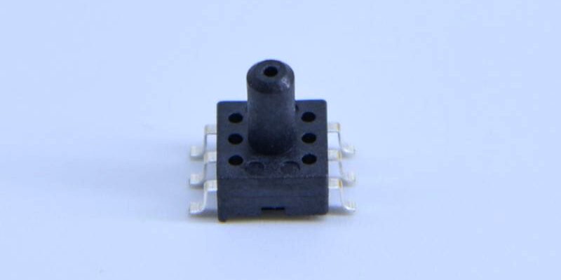
3.1 SOIC-16 dual-port package benefits
Industrial differential sensors often come in an SOIC-16 package and offer vertical or horizontal mounting options, which helps when space is tight. Dual ports let you do reference measurements to cancel out atmospheric pressure drift and make PCB mounting straightforward. Package choice affects heat dissipation, mechanical stress transfer and long-term stability—pick the package orientation and mounting that fit the environment so your filter-monitoring pressure sensor stays reliable over time.
3.2 Benefits of ASIC integration and installation notes
Putting the pressure sensor and a signal-conditioning ASIC into one package provides linearization, temperature compensation, and calibration data, and lets the device output standard signals (mV, 4–20 mA, or digital). That removes the need for external compensation circuitry or complex software correction, cutting integration cost. During installation pay attention to PCB trace layout, grounding and power filtering—these prevent noise from corrupting microvolt-level signals and keep the mV differential sensor producing usable data.
4. Resistance monitoring algorithms and controller integration
4.1 Thresholds, hysteresis and filtering strategies
When the controller receives the differential signal, implement configurable thresholds, hysteresis and time-window filtering to avoid false alarms from transients. Use low-pass filtering to cut high-frequency noise, apply a time window to confirm trends (e.g., alarm only if the value exceeds the threshold for X minutes), and use hysteresis to prevent chatter. Map the 4–20 mA input back to physical differential pressure so operators can instantly see when the filter needs changing, which improves maintenance decisions.
4.2 Decision value of parallel monitoring with flow measurements
Analyzing differential pressure together with flow data from a gas-flow pressure sensor helps distinguish gradual clogging from momentary flow swings. If differential pressure rises and flow drops, that usually indicates increased filter resistance; if differential rises while flow stays the same, it might be a system pressure change or a sensor issue. Parallel monitoring boosts diagnostic power, so the controller can give better maintenance recommendations and cut unnecessary downtime.
5. Engineering considerations and diagnostics
5.1 Error sources from environment & installation
Common error sources include ambient pressure drift, temperature changes, tubing leaks and collapsed hoses. Using a dual-port reference and package-level temperature compensation reduces these errors. Engineers should regularly check zero-point drift, confirm tubing seals and verify tubing placement. Avoid mounting sensors directly in high-vibration or high-EMI areas; use soft hose isolation or shielding if needed to keep readings stable over the long term.
5.2 Diagnostic steps and maintenance recommendations
A diagnostic routine should include: verifying tubing integrity, checking for zero offset, comparing readings against a reference pressure source and logging results. If you see long-term drift, perform an on-site recalibration or replace the sensor. Using the sensor’s calibration mapping (for example, 100 PSI / 20 PSI → 4–20 mA) lets operators quickly check whether the replacement threshold is reached, reducing false alarms and improving maintenance efficiency. Sensors with ASIC conditioning simplify diagnostics.
บทสรุป
Differential pressure sensors provide a direct, linear indicator of filter resistance in gas pipelines. With the right package (e.g., SOIC-16 dual-port), signal-conditioning ASIC, and calibrated mapping to 4–20 mA or digital interfaces (example: 100 PSI / 20 PSI → 4–20 mA), plus solid filtering and threshold strategies, engineers can build reliable filter monitoring and timely maintenance workflows that reduce unexpected downtime and simplify field operations.
บทนำข้างต้นเป็นเพียงรอยขีดข่วนบนพื้นผิวของการประยุกต์ใช้เทคโนโลยีเซ็นเซอร์ความดันเท่านั้น เราจะสำรวจองค์ประกอบเซ็นเซอร์ประเภทต่างๆ ที่ใช้ในผลิตภัณฑ์ต่างๆ ต่อไป วิธีทำงาน ตลอดจนข้อดีและข้อเสีย หากคุณต้องการรายละเอียดเพิ่มเติมเกี่ยวกับสิ่งที่กล่าวถึงที่นี่ คุณสามารถดูเนื้อหาที่เกี่ยวข้องได้ในภายหลังในคู่มือนี้ หากคุณมีเวลาจำกัด คุณสามารถคลิกที่นี่เพื่อดาวน์โหลดรายละเอียดของคู่มือนี้ได้ ข้อมูลผลิตภัณฑ์เซ็นเซอร์ความดันอากาศ.
หากต้องการข้อมูลเพิ่มเติมเกี่ยวกับเทคโนโลยีเซ็นเซอร์อื่นๆ โปรด เยี่ยมชมหน้าเซ็นเซอร์ของเรา.