Katalog
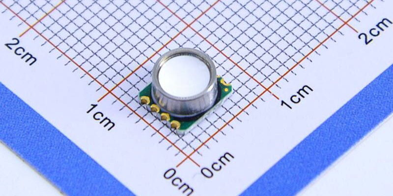
Modern air-filter systems need local positive-pressure monitoring: to tell when a filter’s blocked, to check fan efficiency, and to find leaks. Looking at the WF100 series through-hole package in the picture (top port, five- or six-pin layout), this article walks through sensor selection, mounting interfaces, signal conditioning, temperature and dynamic-response handling, and system verification — a practical guide to improving measurement reliability and implementation.
1. Matching measurement points with sensors
Measurement point selection and range matching
For air-filter duct measurement, the first priority is to place the sensing point where it actually represents upstream/downstream filter pressure — avoid corners and vortex zones. When choosing a 100 kPa sensor or a lower-range device, base that choice on the expected maximum static pressure and differential. For typical filter use, a 0–50 kPa range gives better resolution and linearity. The WF100-style top-port pictured makes it easy to attach a flexible tube, which is convenient for duct-pressure setups.

2. Mechanical and airtight interface design essentials
Mounting seals and hose matching
Airtightness determines how trustworthy duct measurements are. The WF100 top-port sensors need hoses with a matching internal diameter and short, straight runs to avoid dead volumes. Seals should resist oil, dust and ageing; minimise bends and mechanical strain at the connection. If you pick a 0–5 V output positive-pressure sensor, treat electrical and mechanical grounding separately to reduce interference between the casing and the signal reference.
3. Signal conditioning and calibration workflow
Zero, span calibration and temperature offset
For duct-pressure sensors, besides factory specs you must perform on-site zero and span calibration and log ambient temperature to build a compensation table. If a 100 kPa sensor is used but the actual measurements sit in a small subrange (for example 0–20 kPa), scale the range in software to improve effective resolution. For 0–5 V output sensors, match the ADC input impedance and add filtering so sampling noise doesn’t amplify measurement error.
4. Dynamic response, noise and environmental compensation
Response time and interference strategies
Ducts with air filters see fan start/stop events, pulses and short disturbances, so you must balance sensor response and filtering for both real-time needs and stability. Small-volume, directly connected hoses reduce lag. In software, use low-pass filters but keep threshold detection for sudden events so you don’t smooth away meaningful pressure drops. Temperature, humidity and particulate build-up affect long-term stability of air-filter sensors, so include periodic inspections in your validation plan.
5. System integration verification and maintenance essentials
On-site verification steps and troubleshooting
Before commissioning, run comparison tests using a reference pressure source or reference sensor to check the duct pressure readings and verify linearity and drift of 0–5 V output sensors. Log trends for the first 24–72 hours to reveal leaks or grounding issues. Routine maintenance should cover hose replacement, housing checks and straightforward recalibration to keep long-term data usable and reduce false alarms.
Slutsats
Positive-pressure sensors, especially top-port packages like the WF100 family shown, noticeably improve data usability and engineering practicality when measuring air-filter ducts. The keys are range matching (for example using a 100 kPa sensor but refining to the target subrange), solid airtight connections, rigorous zero and temperature-compensation calibration, and a system design that balances response speed and filtering. Proper deployment yields stable analog 0–5 V signals that are easy to collect and use for fault detection, lowering maintenance costs and increasing operational visibility.
Ovanstående introduktion repar bara ytan på tillämpningarna av trycksensorteknologi. Vi kommer att fortsätta att utforska de olika typerna av sensorelement som används i olika produkter, hur de fungerar och deras fördelar och nackdelar. Om du vill ha mer information om vad som diskuteras här kan du kolla in det relaterade innehållet längre fram i den här guiden. Om du är tidspressad kan du också klicka här för att ladda ner detaljerna i denna guide Lufttryckssensor Produkt PDF -data.
För mer information om andra sensorteknologier, vänligen Besök vår Sensors -sida.