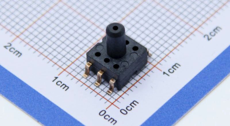
Invasive blood pressure measurement depends on the sensing element’s ability to capture tiny pressure changes reliably and quickly in confined spaces. The sensor shown in the image is an LGA-packaged MEMS device with a metal pressure port (WF-style). Its design lets the pressure medium act directly on the MEMS cavity, minimising intermediate volume and delay — suitable for integration with catheters, infusion lines or cuff interfaces. Key performance factors are sensitivity, response time, temperature compensation and long-term zero stability. These directly affect measurement credibility and the safety of minimally invasive procedures.
The sensors role in minimally invasive measurement systems
1.1 Functional positioning and system integration
In invasive scenarios the sensor serves both as the sampling point and the feedback source. It must support a compact package, corrosion-resistant housing and standard electrical pins for mechanical and electrical mating with catheter ports or monitoring modules.
1.2 Rapid response and high sensitivity requirements
To capture arterial pulse waves and micro-vibrations from blood flow, a sensor must detect changes below 1 mmHg and respond on the millisecond timescale. Response delays or bandwidth limits will shift systolic/diastolic identification and affect clinical interpretation.
Mechanical interface impact on minimally invasive operation
The metal pressure port design determines how the sensor connects to catheters and the sealing reliability. Port diameter, flange geometry and material compatibility affect insertion resistance and the risk of blood or bodily fluid exposure. A well engineered mechanical interface reduces catheter slippage, prevents air bubble ingress and lowers measurement bias — improving safety and data consistency in minimally invasive procedures.

Real-time pressure monitoring and capturing blood-flow signals
2.1 Arterial waveform and pressure fluctuation recognition
When cuff or system pressure drops below arterial systolic pressure, intermittent blood flow produces micro-scale oscillations in the pressure chamber. High-sensitivity MEMS sensors convert those oscillations into electrical signals for algorithms to identify systolic and diastolic points.
2.2 Venting/drainage rate control and sampling strategy
A steady pressure descent (for example 2–3 mmHg per second) must align with the sensor’s sampling rate and anti-alias filtering to avoid signal overlap or spurious pulses. Sampling frequency and filter design should preserve waveform details while suppressing environmental noise.
Signal processing determines measurement accuracy
The sensor’s analogue voltage output requires high-resolution ADC conversion and digital filtering. Appropriate sampling rate, band-pass filtering and waveform detection algorithms separate real blood-flow vibrations from motion artefacts. Incorrect filtering can erase critical peaks or introduce latency, reducing the accuracy of blood pressure determination.
3. Pressure signal conversion, algorithms and error compensation
3.1 Analogue-to-digital conversion implementation
The sensor’s analogue output pairs with a high-resolution ADC (for example 16-bit or higher) and a low-noise front-end amplifier to maintain sub-1 mmHg resolution. Amplifier drift and ADC offset are principal sources of system error.
3.2 Temperature, zero drift and calibration strategies
Temperature-compensation circuitry and an initial auto-calibration routine are essential for stable long-term readings. Auto-calibration can run during idle periods to correct zero drift, reducing the need for manual intervention and improving usability.
Calibration and compensation improve long-term reliability
Sensors experience offset under thermal gradients and mechanical stress. Using built-in temperature sensing and multi-point linearisation reduces environmental influence. Software-side self-checks and calibration prompts protect measurement accuracy while keeping clinical operation manageable.
4. Automatic control and safety mechanisms
4.1 Closed-loop control for inflation and venting
Closed-loop control driven by the sensor’s feedback prevents over-pressure and patient discomfort. Pump speed and valve opening are adjusted based on real-time pressure curves to achieve smooth inflation and controlled depressurisation.
4.2 Fault detection and protection logic
Sensor faults — such as short, open-circuit or sudden drift — should trigger fallback measurement paths or a safe stop to protect the patient and notify maintenance. The system ought to log key diagnostic parameters for traceability and measurement quality verification.
5. Design trade-offs and engineering implementation points
5.1 Packaging and material choices
For medical invasive use, priority is given to stainless steel or medical-grade alloys for the pressure port and surface finishing to resist corrosion and ensure biocompatibility. Combining LGA packaging with a metal port keeps miniaturisation while offering robust mechanical connection.
5.2 Balancing power, bandwidth and communication interfaces
Invasive devices often have limited power budgets. Low-power sensor and frontend designs must be balanced against required bandwidth and signal integrity to ensure performance during critical measurement windows.
Practical considerations for integration and production
From an engineering viewpoint, sensor design must also meet manufacturability and consistency requirements. Pad layout, lead-frame processes, port sealing and test flows affect yield. Strict test specifications and factory calibration reduce field issues and strengthen customer confidence.
Slutsats
By combining miniature MEMS pressure cores with metal pressure ports, invasive blood pressure sensors enable high-sensitivity, low-latency pressure acquisition under minimally invasive conditions. Engineering implementation must balance mechanical interface design, signal-chain architecture, calibration and closed-loop control to ensure measurement consistency and safety. For technical decision-makers, key evaluation criteria are sensor sensitivity, bandwidth, temperature compensation and packaging compatibility when assessing integration options.
Ovanstående introduktion repar bara ytan på tillämpningarna av trycksensorteknologi. Vi kommer att fortsätta att utforska de olika typerna av sensorelement som används i olika produkter, hur de fungerar och deras fördelar och nackdelar. Om du vill ha mer information om vad som diskuteras här kan du kolla in det relaterade innehållet längre fram i den här guiden. Om du är tidspressad kan du också klicka här för att ladda ner detaljerna i denna guide Lufttryckssensor Produkt PDF -data.
För mer information om andra sensorteknologier, vänligen Besök vår Sensors -sida.