Каталог
Да почнеме да разбираме!
Introduction to Differential Pressure Sensors
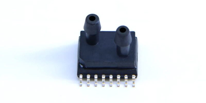
WF has launched a new internal integration of 16-bit MCU differential pressure sensor WF200DP, its range of ± 5000pa (5000pa can be measured below), the typical output accuracy of ± 0.1% FS, the factory has done the temperature compensation and pressure calibration, the temperature compensation range of -20 ° C to 85 ° C, support for I2C and analog output. It has been successfully applied in German ventilator products, mainly through the differential pressure sensor to realize the measurement of respiratory flow.
Many engineers in the use of WF200DP, may encounter different technical problems, the following is based on a customer’s actual debugging WF200DP pressure sensor process, I hope to give other engineers to give reference!
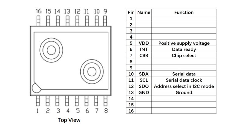
First of all, the differential pressure sensor WF200DP can work in 3V or 5V system, support for standard I2C communication, engineers can use analog I2C, you can also use hardware I2C. many engineers are asking about the I2C address of the WF200DP, the original factory set to 0x30.
Second, the differential pressure sensor WF200DP I2C output value range of -26214 to +26214, while the analog output corresponds to the voltage range of 10% * VDD to 90 * VDD, the two ways correspond to the range of -5000pa to 5000pa respectively, so through this you can calculate the slope of the linear straight line.
�ен сензор за диференцијален притисок")
Three different filtering parameters for external differential pressure sensor MCU
Differential pressure sensor WF200DP internal integrated low-pass filter, through the external MCU can set three different filter parameters:
1. For cutoff frequency fc=10hz, set Part numbers 11, 12, 13;
2. When the cutoff frequency fc=20hz, set Part numbers 21, 22, 23;
3. When the cutoff frequency fc=50hz, set Part numbers 51, 52, 53;
Differential Pressure Sensor Temperature Compensation
Differential pressure sensor WF200DP factory temperature compensation range is -20 ℃ to 85 ℃, you can refer to the picture below. The actual product requires -40℃ to 85℃, the middle temperature range without compensation needs to be compensated by the engineer himself in the external MCU. The compensation method can be based on a gradient of 5 ℃ for temperature, pressure test, read the data after the curve fitting.
Differential Pressure Sensor Typical Circuit
The typical circuit of the differential pressure sensor WF200DP is shown below, and many engineers are asking about the role of pin 13. This pin is WF original factory debugging use, customers in the use of differential pressure sensor WF200DP only need to connect the pin to GND.
Differential Pressure Sensor Register Address
The measurement results of the differential pressure sensor WF200DP are stored in a 2-byte result register, with the temperature result register at address 0x2E, the pressure result register at address 0x30, and the status result register at address 0x32. Many engineers just need the pressure value, so the MCU just needs to read the value of the 0x30 register, and then calculates the current pressure by comparing it with the slope of a straight line. value. Note: Differential Pressure Sensor WF200DP defaults to low byte first and high byte second.
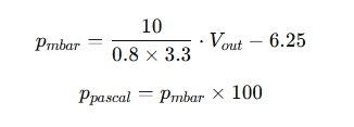
Pcounts=256*byte2+ byte1 If the engineer uses the differential pressure sensor WF200DP for analog output, for example, in a 3V system, the -5000pa output voltage is 0.3V, and the 5000pa output voltage is 3.3V, according to which the slope is calculated, and then the pressure value is calculated by the following formula, in mbar.
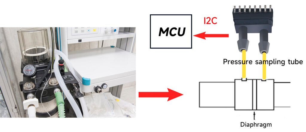
WF ±5000pa Differential Pressure Sensor WF200DP can be utilized for flow measurement in ventilators. Ventilator products, is the use of a flow module to realize the air flow through the tube diaphragm, due to the diaphragm of the circulation cross-section than the pipe cross-section is small, the air flow to form a local contraction, will be formed before and after the diaphragm 2,000pa pressure difference, the WF200DP to detect the amount of change in the pressure difference.
Differential Pressure Sensor Commissioning
At the time of design, the damping coefficient of the flow module will affect the accuracy of the differential pressure sensor, and the WF200DP is based on the silicon design principle of MEMS, while the WF200DP comes with -20 ℃ to 85 ℃ temperature compensation, it will be adapted to most of the flow module on the market. WF200DP is to support digital I2C output, WF200DP debugging process with other brands is not universal, the following share about WF200DP debugging experience.
In the hardware circuit, the WF200DP requires pin 13 to be connected to GND to ensure zero-degree drift accuracy.The SDA pin of the WF200DP is for serial data and the SDO pin is for I2C output.

Hardware circuit diagram of WF200DP
Sensor I2C address
The WF200DP supports standard I2C communication and the default I2C address is 0x30. 2 bytes are used inside the WF200DP to store the pressure, temperature and status data respectively, where 0x2E stores the temperature value, 0x30 stores the pressure value and 0x32 stores the status register. It is important to note that 0x32 can only be read after 0x30 has been read first.
Filter Setup
The WF200DP supports three different filters, when the filter is set to 11, 12, 13, the cutoff Fc = 10hz, when the filter is set to 21, 22, 23, the cutoff Fc = 20hz, and when the filter is set to 51, 52, 53, the cutoff Fc = 50hz, and the filter values inside the WF200DP are set in turn to achieve the corresponding frequency with the Adoption of precision fully meets the requirements of the respirator program.
Read results
While reading the result, the WF200DP output format is low byte first and high byte second. After reading the result, the pressure value P=256*byte2+byte1 is calculated in the MCU.In the same way, the temperature value is also calculated.
Secondary calibration process
If the I2C output accuracy cannot meet the requirements of the respiratory products, the analog output can be used directly, and the analog voltage of WF200DP can be calibrated twice by an algorithm in the MCU to improve the measurement accuracy of SM9391. If VCC=3V, the calibration pressure range is -5mba to 5mbar, corresponding to the WF200DP requires the output amplitude to be 10%*VCC to 90%*VCC, then the secondary calibration process is as follows:
The nonlinearity error after calibration is fully guaranteed to be within 0.1%FS, or even higher.
Hope the above experience can help every engineer to speed up the design progress of pressure sensor WF200DP.
Заклучок
This article describes in detail the application and commissioning process of the WF200DP differential pressure sensor in ventilator products.With a range of ±5000Pa, an output accuracy of ±0.1%FS, and support for I2C and digital output, the WF200DP has been successfully applied to German ventilator products and is mainly used to realize the precise measurement of respiratory flow. Through in-depth analysis of I2C communication, digital output, low-pass filter setting and temperature compensation, this paper helps engineers master how to improve the accuracy and performance of WF200DP by optimizing the hardware design and calibration process.
Горенаведениот вовед само ја гребе површината на апликациите на технологијата на сензорот за притисок. Ќе продолжиме да ги истражуваме различните типови на сензорски елементи што се користат во различни производи, како тие функционираат и нивните предности и недостатоци. Ако сакате повеќе детали за она што се дискутира овде, можете да ја проверите поврзаната содржина подоцна во ова упатство. Ако сте притиснати за време, можете исто така да кликнете овде за да ги преземете деталите за овој водич Податоци за производ на сензорот за притисок на воздухот PDF.
За повеќе информации за други технологии на сензори, ве молиме Посетете ја страницата на нашите сензори.