ລາຍການ
This expanded article delves into integrating the WF100DP ±20 kPa MEMS digital pressure sensor in NPWT devices, addressing physiological principles, system architecture, performance optimization, installation and soldering best practices, and pre-production testing. The detailed technical roadmap guides engineers, procurement managers, and technical decision-makers through reliable, high-precision solutions for faster wound healing and reduced infection risk.
1. NPWT Principles and Sensor Requirements
1.1 Physiological Mechanism of Negative Pressure Healing
Negative Pressure Wound Therapy (NPWT) creates a controlled sub-atmospheric environment at the wound site to accelerate healing. By applying sustained or intermittent negative pressure, NPWT promotes granulation tissue formation, enhances angiogenesis, and continuously evacuates exudate and necrotic debris, thereby reducing bacterial load.
1.2 Clinical Pressure Range and Sensor Coverage
Clinically, NPWT operates between –50 and –125 mmHg (–6.7 to –16.7 kPa). The WF100DP ±20 kPa MEMS sensor covers this range with ample margin, offering 0.5% full-scale (FS) accuracy even near –16.7 kPa to ensure reliable readings.
1.3 Dynamic Response and Digital Interfaceility
Fast dynamic response is crucial: wound conditions change rapidly, requiring pump and valve adjustments in milliseconds. The WF100DP’s built-in 24-bit ADC and digital I²C/SPI interface achieve pressure detection and data update within 1 ms, eliminating external amplification and filtering circuits while enhancing EMI immunity.
1.4 Long-Term Stability and Drift Compensation
Long-term stability is vital in medical settings where temperature, humidity, and vibration can induce zero-point drift or sensitivity shifts. The WF100DP undergoes multi-point factory temperature calibration and features internal compensation to limit drift to ±0.1 kPa. An onboard zero-point auto-calibration function allows periodic recalibration in no-pressure states.
1.5 Packaging and Biocompatibility
Form factor and packaging also matter for system integration. The SMD WF100DP measures just 10 × 8.5 × 9 mm, mounting flush on the mainboard with minimal pneumatic routing. Its glass-fiber–reinforced engineering plastic housing offers biocompatibility and mechanical strength, meeting medical device safety requirements.

2. Solution Highlights and System Architecture
2.1 Digital Bus Integration
In an NPWT device, the MEMS sensor must seamlessly integrate with the main control board using digital interfaces such as I²C or SPI, eliminating the need for analog amplification and reducing EMI vulnerability.
2.2 Signal Integrity and Filtering
Upon data acquisition, raw pressure readings undergo CRC checks followed by Kalman filtering to merge the noisy sensor output with the dynamic system model, yielding a smooth, accurate pressure signal for closed-loop control.
2.3 Closed-Loop Pump and Safety Valve Control
The filtered data feed a PID controller that adjusts the vacuum pump speed in real time, ensuring the wound chamber maintains the target negative pressure of –50 to –125 mmHg. A hardware safety valve, triggered by an overpressure threshold, provides fail-safe protection by instantaneously venting excess vacuum.
2.4 Multi-Zone Monitoringtion & Cleaning
For large or compartmentalized wounds, multiple WF100DP sensors can be deployed in parallel—each assigned a unique I²C address or SPI chip-select pin—enabling independent monitoring and zone-specific PID loops.
2.5 Data Logging and HMI Integration
Data logging of each sensor channel supports traceability and remote diagnostics via a touchscreen HMI or Bluetooth-enabled app, facilitating real-time visualization of pressure curves and device status.
3. Performance Optimization and Long-Term Stability
3.1 Factory Temperature Calibration
WF100DP incorporates laser-trimmed resistors for multi-point factory temperature calibration from –10 °C to 60 °C, referenced against an internal temperature sensor, reducing thermal drift to < ±0.1 kPa.
3.2 Real-Time Compensation Algorithms
During operation, the MCU applies first-order linear compensation based on real-time temperature readings, ensuring stable pressure output in both operating theatres and home-care settings.
3.3 Moisture and Particulate Protection
To guard against moisture intrusion, a medical-grade 0.2 µm microporous filter covers the sensor port, blocking exudate and particulates without impeding gas flow.
3.4 Vibration and Shock Mitigation
Vibration-isolating mounts and flexible silicone tubing attenuate pump-induced oscillations in the 100–200 Hz band, preventing resonant amplification that could stress the MEMS die. The sensor’s shock tolerance of ≥10 g protects it from accidental drops.
3.5 Accelerated Life Testing and MTTF Modeling
Accelerated life tests—85 °C/85 % RH for > 1 000 h—combined with 100 000 pump cycles, quantify drift and failure rates, feeding statistical models (Arrhenius, Weibull) to predict MTTF and set warranty periods.

4. Installation and Soldering Precautions
4.1 Port Orientation and PCB Keep-Out
On the PCB, orient the WF100DP port toward a designated cutout or keep-out zone to provide unhindered air access and prevent copper foil shadowing.
4.2 Tubing Selection and Clearance
Leave a minimum 2 mm clearance around the port for tubing attachment; use medical-grade, low-rebound silicone tubing with ±0.05 mm tolerance to minimize dead volume and eliminate microleaks.
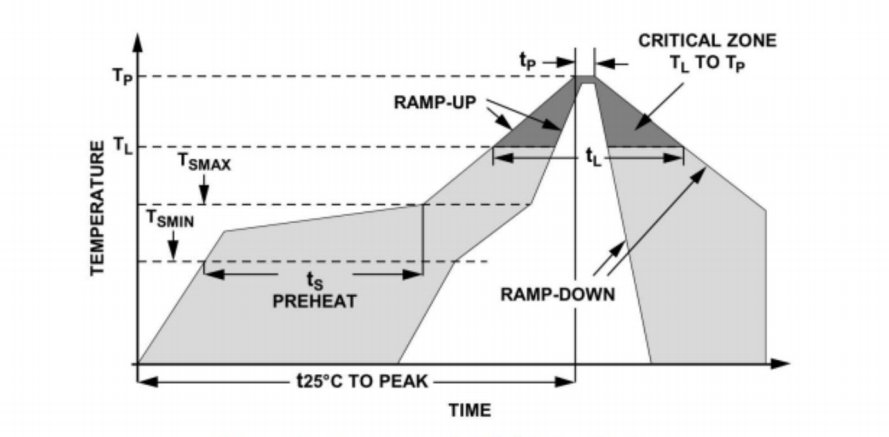
4.3 Reflow Profile and Thermal Recovery
Employ a lead-free reflow profile peaking at ≤ 260 °C with ≤ 3 °C/s ramp rates; post-reflow, allow a 24 h rest for thermal stress relaxation before calibration.
4.4 Manual Soldering Guidelines
If hand-soldering is unavoidable, use a ≤ 25 W iron at ≤ 320 °C for no more than 3 s per pad, avoiding repeated heating cycles that could damage the MEMS cavity.
4.5 Port Protection and Cleaning
After assembly, apply a 0.2 µm filter or dust cover on the port. Clean with low-pressure air or 70 % isopropanol swabs; never expose the port to high-pressure jets or solvents.
5. Pre-Production Testing and Measurement Tools
5.1 Automated Calibration Bench
The automated bench comprises a precision ±20 kPa pressure source (deadweight tester or electronic calibrator), a –10 °C to 60 °C environmental chamber, and a 0.1 % FS reference sensor for traceable comparison.
5.2 Calibration Software and Scripts
Calibration software scripts impose static and dynamic pressure profiles, record WF100DP outputs, compute gain and offset coefficients, and program these into the sensor’s EEPROM.
")
5.3 Key Test Metrics
Key test metrics include linearity (sampling at 25, 50, 75 % FS), hysteresis (forward/backward sweep comparison), repeatability (± 3σ over 20 cycles), zero-point drift, and temperature drift.
5.4 Automated Test Fixtures
Custom test fixtures—MCU dev boards with I²C/SPI connectors—enable automated data capture and connectivity to MES for serial-number tracking and pass/fail analysis.
5.5 First Article and Capability Studies
After small-batch validation, execute First Article Inspections (FAI) and statistical process capability studies (Cp/Cpk ≥ 1.33) to confirm production readiness and meet procurement standards.
ສະຫຼຸບ
Integrating the WF100DP ±20 kPa MEMS digital pressure sensor into NPWT systems ensures precise control of therapeutic negative pressures (–50 to –125 mmHg) for faster wound healing and reduced infection risk. Its 24-bit ADC with I²C/SPI output and ≤1 ms response eliminates analog circuitry and boosts EMI immunity. Factory temperature calibration and internal compensation keep drift under ±0.1 kPa (–10 °C to 60 °C), while ≥10 g shock tolerance and vibration damping protect the MEMS die. Lead-free reflow profiles (≤260 °C, ≤3 °C/s ramps) and post-reflow rest prevent thermal stress. A full pre-production test bench, ISO 80601-2 compliant with FAI and Cp/Cpk ≥ 1.33, guarantees each sensor meets ±0.5 % FS specs before mass deployment, delivering reliable, scalable NPWT performance.
ການແນະນໍາຂ້າງເທິງພຽງແຕ່ scratches ດ້ານຂອງຄໍາຮ້ອງສະຫມັກຂອງເຕັກໂນໂລຊີເຊັນເຊີຄວາມກົດດັນ. ພວກເຮົາຈະສືບຕໍ່ຄົ້ນຫາປະເພດຕ່າງໆຂອງອົງປະກອບເຊັນເຊີທີ່ໃຊ້ໃນຜະລິດຕະພັນຕ່າງໆ, ວິທີການເຮັດວຽກ, ແລະຂໍ້ດີແລະຂໍ້ເສຍຂອງມັນ. ຖ້າທ່ານຕ້ອງການລາຍລະອຽດເພີ່ມເຕີມກ່ຽວກັບສິ່ງທີ່ໄດ້ສົນທະນາຢູ່ທີ່ນີ້, ທ່ານສາມາດກວດເບິ່ງເນື້ອຫາທີ່ກ່ຽວຂ້ອງໃນພາຍຫຼັງໃນຄູ່ມືນີ້. ຖ້າຫາກວ່າທ່ານກໍາລັງກົດດັນສໍາລັບການໃຊ້ເວລາ, ທ່ານຍັງສາມາດຄລິກທີ່ນີ້ເພື່ອດາວໂຫລດລາຍລະອຽດຂອງຄູ່ມືນີ້ ຂໍ້ມູນ PDF ຜະລິດຕະພັນ PDOR Air.
ສໍາລັບຂໍ້ມູນເພີ່ມເຕີມກ່ຽວກັບເຕັກໂນໂລຊີເຊັນເຊີອື່ນໆ, ກະລຸນາ ເຂົ້າເບິ່ງຫນ້າສັນຍາລັກຂອງພວກເຮົາ.


