- 에 의해 WF센서
This piece focuses on the kinds of errors that affect sensor accuracy and the practical engineering responses. The aim is to help you quickly spot system bottlenecks and choose workable fixes. By picking the right hardware, optimising system design and cleaning up the signal chain, you can noticeably improve the stability and repeatability of high-precision pressure sensors in real products.
목록
1. Overall framework of sensor accuracy errors
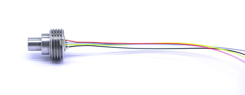
In a measurement system, error rarely comes from one place — it’s the sum of contributions from several subsystems. You can think of overall accuracy as the combined effect of the reference source, front-end amplification, the sensing element itself, environmental coupling and the digital conversion stage. When designing, take a systems view: an offset or gain error at one point will be amplified, filtered and converted downstream, often turning a small hardware imperfection into a noticeable output error. Quantifying how sensitive the system output is to each element lets you focus resources where they buy the most improvement. The pictured sensor connector — a small metal housing — is a good example: its packaging and mounting affect thermal and mechanical coupling, which in turn changes how the sensor responds.
Error classification and system-level impact
Errors generally fall into four types: offset (bias), scale error (gain), nonlinearity and noise. Offset shifts the whole reading; scale error changes proportional readings across the range; nonlinearity shows up differently at different parts of the range; and noise sets the smallest detectable change within a given bandwidth. System-level analysis means giving each error source a sensitivity coefficient, building an error budget and worst-case stacking those contributions. That gives you the evidence to decide where to improve hardware, or where software compensation will be sufficient.
2. Fundamental impact of power and references on accuracy
Reference sources are foundational because the measurement is ultimately compared to that reference. A carefully designed reference drastically reduces temperature-induced drift and long-term bias. For example, in common operating ranges, a tiny temperature coefficient in the reference can translate to a significant fraction of full-scale error. So, choose low-drift, low-noise reference parts and pay attention to layout: decoupling, grounding and shielding matter. On the firmware side, periodic checks or software-based calibration routines can correct slow drifts in the reference over time.
How supply quality and reference design contribute to measurement bias
A stable supply needs low output impedance and appropriate decoupling, especially for small-signal measurements where transient voltage steps become measurement errors. Provide local decoupling at sensitive nodes and consider staged regulation and filtering. In space-limited devices, keep analogue references physically separated from noisy digital switching areas to avoid coupling. Good PCB layout and power domain separation reduce injected errors significantly.
3. Noise and drift in amplifiers and the small-signal chain
In the small-signal chain, amplifier choice largely sets the achievable signal-to-noise ratio. Amplifier offset and drift convert to equivalent measurement errors at the input — in small full-scale systems a tiny input offset can mean several percent error at the output. Achieving low noise and high dynamic range is a balancing act: device selection and topology both matter. Practically, you’ll use a low-noise, high-input-impedance front-end stage and follow with gain stages to reach the required overall amplification while keeping bandwidth adequate for the measurement frequencies.
Design trade-offs for amplifier circuits
Single amplifiers rarely deliver both very low noise and very high gain. A multi-stage approach commonly works best: a low-noise input amplifier preserves the weak signal, while later stages add controlled gain and drive capability. Filters must be chosen to match sampling rates so you avoid aliasing and preserve the signal of interest. Carefully balance input impedance, noise performance and DC offset when picking parts or topologies.
4. Manufacturing and assembly limits of the sensing element
Errors from the sensing element itself — manufacturing tolerances, material variability and assembly stresses — are often the hardest to remove. Even with factory linearisation, outputs vary noticeably device-to-device. Many pressure sensors use a bridge excitation to create a proportional output; that helps reduce drift, but bridge asymmetry and assembly stress still produce offsets. The small metal-housed connector shown in the image is handy for cramped installations but brings thermal paths and stress transfer that can affect readings; so think about mechanical isolation and careful thermal design during product integration.
How mechanics and installation affect readings locally
Mounting location and mechanical connection change local temperature distribution and the stress state around the sensing element, causing static offsets or altered nonlinearity. Good mechanical design aims to minimise forces transmitted to the sensitive core and, where needed, uses flexible mountings or compensation features to isolate unwanted stresses.
5. A/D conversion and digitalisation limits
The A/D stage often dictates the usable resolution: a device rated with many bits can be noise-limited well below that nominal resolution. Distinguish between nominal bits and effective bits — the latter depend on the RMS noise floor. Peak-to-peak noise is related statistically to the RMS value, so you should evaluate converters on noise inside the actual application bandwidth. Also be cautious: datasheet conditions (reference voltage, input range, bandwidth) may differ from your product’s conditions; measure the effective resolution in the real setup, not just on paper.
System-level measurement strategies and error compensation methods
In the digital domain you can apply filtering, averaging and calibration tables to reduce residual errors. Filtering trades bandwidth for improved SNR; averaging removes random noise but can smear time-domain features. Software calibration can correct static offset and scale, but it doesn’t fully compensate dynamic errors caused by temperature shifts or mechanical stresses. A combined hardware-and-software approach is therefore the most robust.
결론
Raising accuracy is a system-level task. Pay attention to references and supplies, the amplifier front end, the sensing element and its mechanical packaging, and the A/D stage. For the small metal-housed connector shown, take special care over mechanical and thermal paths. When selecting amplifiers and converters, make noise and dynamic range your primary criteria. Build an error budget that quantifies each subsystem’s contribution so you can prioritise improvements where they matter most. A mix of low-noise hardware design and targeted digital compensation will noticeably boost the in-field performance of high-precision pressure sensors 그리고 high-resolution pressure sensors — and when using oil-filled pressure sensor modules 또는 diffusion-silicon oil-filled cores, an integrated systems view and careful implementation are essential.
위의 소개는 압력 센서 기술 적용의 표면적인 부분에 불과합니다. 우리는 다양한 제품에 사용되는 다양한 유형의 센서 요소, 작동 방식, 장점과 단점을 계속해서 탐구할 것입니다. 여기에서 논의된 내용에 대해 더 자세히 알아보려면 이 가이드 뒷부분의 관련 콘텐츠를 확인하세요. 시간이 촉박한 경우 여기를 클릭하여 이 가이드의 세부정보를 다운로드할 수도 있습니다. 공기 압력 센서 제품 PDF 데이터.
다른 센서 기술에 대한 자세한 내용은 다음을 참조하십시오. 센서 페이지를 방문하십시오.


