목록
스마트워치 혈압 모니터링은 마이크로 펌프와 고해상도 압력 센서 간의 정밀한 조정에 의존합니다. WF3050D 디지털 MEMS 센서를 중심으로 이 기사에서는 요구 사항 분석, 센서 선택, 시스템 통합부터 설치/납땜 모범 사례 및 사전 생산 테스트 도구에 이르기까지 엔드투엔드 솔루션을 제공합니다. 이 접근 방식은 초소형 크기, 저전력, 높은 정확도의 균형을 유지하여 신속한 타당성 평가 및 배포를 가능하게 합니다.
참고용으로만 사용하세요
애플리케이션 배경 및 요구 사항 분석
스마트워치 혈압 기능은 작은 공간 내에서 압력 변화를 제어해야 합니다. 마이크로 펌프는 1cm3 미만에 맞아야 하며 0~50kPa를 생성해야 합니다. 센서에는 ±1%FS 정확도, 디지털 출력, 낮은 드리프트(≤0.5%FS/°C), 대기 전류가 필요합니다. <10μA 및 활성 <1mA. 손목의 동작 및 온도 변화는 안정성 문제를 야기하며 명확한 펄스 파형 캡처를 위해 ≥200Hz 샘플링이 필요합니다. 엔지니어는 레이아웃, 전원 설계 및 알고리즘 통합의 균형을 유지해야 하며, 조달 관리자는 공급 일관성과 생산 수율에 중점을 둡니다.
1.1 공간 및 전력 제약
초소형 모듈은 열 방출 및 충격 복원력에 주의를 기울여 펌프, 튜브 및 센서를 결합합니다.
전체적인 전력 소모가 낮아 시계 용량에 맞춰 배터리 수명이 연장됩니다.
1.2 정확성과 반응성
±1%FS는 의료 모니터링 표준을 충족합니다.
≥200Hz 샘플링은 앨리어싱 없이 전체 펄스 파형을 캡처합니다.
1.3 인터페이스 호환성
WF3050D의 PDM/I²S 디지털 인터페이스는 PCB 복잡성을 줄여줍니다.
MCU와의 빠른 버스 통합으로 펌웨어 설계가 단순화됩니다.
센서 선택 및 매개변수 일치
MEMS 센서 중에서 WF3050D는 3.0×5.0×0.93mm 크기, 0~50kPa 범위, 디지털 I²S/PDM 및 0.48%FS/°C 드리프트를 자랑합니다. 일반적인 정확도 ≤±0.5%FS는 최대 200mmHg까지 혈압 추적을 지원합니다. 작동 전압 1.7~3.6V는 워치 레일과 일치하며 외부 ADC가 필요하지 않습니다. 상단 포트 설계로 가스 라우팅이 용이합니다. 금속 뚜껑은 충격 저항을 추가합니다.
2.1 범위와 정밀도
0–50kPa는 95~200mmHg 임상 창을 포함합니다.
비선형성 ≤±0.3%FS 및 높은 반복성.
2.2 열적 거동
드리프트 ≤0.48%FS/°C, 1차 보상으로 더욱 개선되었습니다.
응답 시간 <급격한 압력 변화에는 2ms가 소요됩니다.
2.3 전기적 적합성
MCU에 대한 직접 디지털 출력은 소음과 전력을 줄입니다.
저전압 시동으로 빠른 절전 모드 해제가 가능합니다.

시스템 통합 및 마이크로 펌프 설계
가스 라우팅, 기계적 지원 및 EMC 설계에 대한 센서와 펌프 힌지의 효과적인 협업.
가스 라우팅: 짧은 실리콘 튜빙(≤5mm, Ø1.2mm)으로 불감부피를 최소화합니다.
기계적 장착: 이중층 댐핑 폼을 적용한 알루미늄 브래킷으로 진동을 줄여줍니다.
EMC 관행: 디지털 라인 주변에 필터 캡과 접지면을 배치하여 노이즈를 억제합니다.
펌웨어 교정: 온도 드리프트 보상으로 시작 시 자동 영점 교정.
3.1 가스 경로 최적화
챔버 용량이 10μL 이하이면 잔류 공기가 차단됩니다.
저흡수성 튜브는 가스 정체를 방지합니다.
3.2 진동 차단 & 열 제어
진동 감쇠 패드는 기계적 소음을 줄여줍니다.
센서 아래의 구리 열 패드는 온도 균일성을 촉진합니다.
3.3 펌웨어 알고리즘
시작 자동 교정, 지속적인 드리프트 보정.
디지털 필터를 사용한 고속 샘플링은 속도와 안정성의 균형을 유지합니다.
설치 및 납땜 참고 사항
적절한 배치와 납땜은 성능과 수율에 매우 중요합니다.
정위: 막힘을 방지하기 위해 상단 포트를 펌프 경로쪽으로 정렬하십시오.
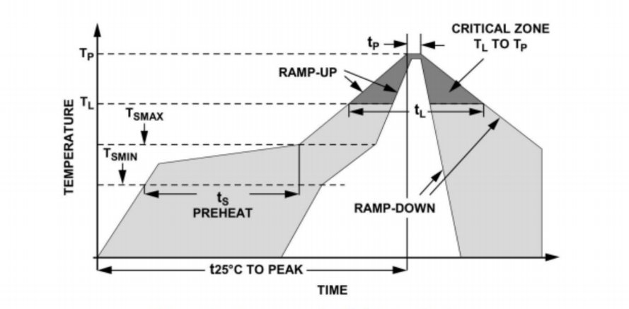
리플로우 프로파일: 230~260°C 영역에서 10~20초 동안 최고 260°C 이하.
솔더 페이스트: SnAgCu3.0, 45–75μm 입자로 안정적인 접합을 보장합니다.
PCB 패드 디자인: 차폐를 위한 센서 아래의 대형 접지 패드, 접지면 주변.
먼지 & 수분 보호: 오염방지를 위해 장착 후 즉시 포트를 밀봉해 주세요.
4.1 SMT 프로세스 곡선
예열: 120~150°C → 담그기: 150~180°C → 리플로우: 230~260°C → 냉각, ≤4°C/s.
페이스트 두께: 100-120μm.
4.2 리플로우 후 검사
AOI는 0.1mm 공차 내에서 배치를 확인합니다.
X-레이를 통해 보이드 없는 솔더 조인트가 확인되었습니다.
사전 생산 테스트 및 측정 도구
대량 생산 전에 일관성을 보장하기 위해 다단계 테스트를 설정하십시오.
기능 점검: 0/20/40kPa에서 교정된 가스 소스, 지점 전체에 걸쳐 오류를 기록합니다.
환경적 스트레스: 드리프트를 평가하기 위해 48시간 동안 85°C/85%RH.
진동 & 충격: 10~2000Hz @5g, 30분.
EMC 규정 준수: IEC61000-4에 따른 방사 및 전도 내성.
장비:
정밀 가스 교정 벤치(0.1Pa 분해능)
고속 DAQ(≥2kHz).
보드 처리 기능을 갖춘 자동화된 테스트 픽스처.
5.1 교정 작업 흐름
예열 5분 → 표준 압력 적용 → 출력 기록 → 선형성 계산 & 오프셋 → 교정 곡선을 생성합니다.
5.2 데이터 추적성
전체 추적을 위한 센서 배치 코딩.
MES에 자동으로 데이터를 로그인하면 품질 분석이 가능해집니다.
결론
이 가이드에서는 WF3050D 디지털 MEMS 압력 센서를 스마트워치 마이크로 펌프 혈압 시스템에 통합하기 위한 엔드투엔드 솔루션을 자세히 설명합니다. 요구 사항 분석, 센서 선택, 시스템 통합, 설치 모범 사례 및 사전 생산 테스트를 다루는 이 솔루션은 소형화, 저전력, 정밀도 및 신뢰성을 보장하여 엔지니어 팀이 고성능 스마트워치 혈압 기능을 자신 있게 배포할 수 있도록 지원합니다.
위의 소개는 압력 센서 기술 적용의 표면적인 부분에 불과합니다. 우리는 다양한 제품에 사용되는 다양한 유형의 센서 요소, 작동 방식, 장점과 단점을 계속해서 탐구할 것입니다. 여기에서 논의된 내용에 대해 더 자세히 알아보려면 이 가이드 뒷부분의 관련 콘텐츠를 확인하세요. 시간이 촉박한 경우 여기를 클릭하여 이 가이드의 세부정보를 다운로드할 수도 있습니다. 공기 압력 센서 제품 PDF 데이터.
다른 센서 기술에 대한 자세한 내용은 다음을 참조하십시오. 센서 페이지를 방문하십시오.


