カタログ
1. 空気圧プレスにおけるチップの測定原理
1.1 チップパッケージの概要
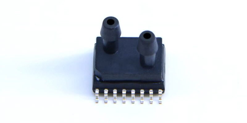
MEMS 差圧センサー チップは、圧力ライン用のデュアル マイクロポート バーブを備えた SOP16 または DFN パッケージで提供され、PCB に直接 SMD 実装されています。チップ底部のパッドは、電源、信号、およびグランド接続を提供します。
1.2 微細構造とひずみの検出
薄いシリコンのダイヤフラムが 2 つのマイクロキャビティの間にあります。差圧によりミクロンスケールのたわみが生じ、これが統合された抵抗ブリッジまたは容量素子によって感知され、電気信号に変換されます。
1.3 信号調整と出力
内蔵の低ノイズアンプと温度補償回路は、標準の 0.5 ~ 4.5 V アナログ信号またはオプションの I²C/SPI デジタル インターフェイスを出力し、PLC または組み込み MCU の統合に対応します。
1.4 温度ドリフトと線形化
オンチップ EEPROM に保存された校正データは温度ドリフトとゼロ オフセットを補正し、-40 °C ~ +125 °C で 0.2% FS よりも優れた精度を保証します。
差動圧力センサー")
2. パフォーマンスの利点と要件
2.1 高集積化と軽量化
チップのコンパクトなパッケージとマイクロバーブポートにより体積と重量が削減され、小型の空気圧モジュールに最適です。
2.3 耐振動性および耐衝撃性
シリコン MEMS 構造は最大 20 g の衝撃と 10 g の振動に耐え、空気圧プレスの動的スイッチングに適応します。
2.4 費用対効果と量産性
標準的な半導体製造と SMD アセンブリによりユニットあたりのコストが削減され、拡張可能な導入が可能になります。

3. 実装およびリフローはんだ付けに関する考慮事項
3.1 PCB の設計とレイアウト
ポートにアクセスできるように、チップの周囲にスペースを確保します。
メーカーの推奨に従ってパッドを設計し、洗浄不要、鉛フリーのリフロー ペースト ステンシルと互換性があります。
3.2 リフロープロファイル制御
ピーク温度は 260 °C 未満、総リフロー時間は 60 秒未満。
最初に電気パッドをはんだ付けし、次に低温接着剤または局所的なはんだ付けでポート インターフェイスを固定します。
3.3 チューブの接続とシール
少なくとも 3 mm の挿入深さのマイクロバーブに適合するサイズの柔らかいシリコン チューブを使用します。
振動による緩みを防ぐために、小型クランプまたは熱収縮チューブを使用して接続を強化します。
3.4 ESD とクリーニング
配置の前後に厳格な ESD プロトコルに従い、イオン化空気または IPA でフラックス残留物を除去してください。
MEMS 構造を保護するために、塩素系クリーナーの使用は避けてください。
4. ケーススタディとパフォーマンスの検証
4.1 小規模空気圧アセンブリの監視
スマート デバイスのハウジング ラインでは、センサー チップがシリンダーの力を追跡して適切な挿入を保証し、歩留まりが 5% 向上しました。
4.2 オンライン診断とアラート
公称差圧から 10% 逸脱すると、ラインの詰まりや漏れの可能性についてシステム アラートが発せられ、迅速なメンテナンスが可能になります。
4.3 データ統合とクラウドプラットフォーム
I²C データは MCU によって変換され、MQTT 経由でクラウドに送信され、そこで分析によって機器の状態が予測されます。
4.4 長期安定性試験
3000 時間の動作後もドリフトは 0.5% FS 未満に留まり、ハイサイクル用途への適合性が確認されました。
結論
MEMS 差圧センサー チップは、空気圧プレス用途にコンパクトな統合、迅速な応答、堅牢な干渉耐性、およびコスト効率の高い大量生産を提供します。信頼性の高いパフォーマンスを確保するには、適切な PCB レイアウト、制御されたリフローはんだ付け、安全なチューブ、および ESD 対策が不可欠です。このソリューションは、自動化された組立プロセスに正確、軽量、効率的な監視サポートを提供します。
上記の紹介は、圧力センサー技術のアプリケーションの表面をなぞっただけです。私たちは、さまざまな製品で使用されているさまざまなタイプのセンサー素子、それらがどのように機能するか、そしてそれらの長所と短所を引き続き調査していきます。ここで説明する内容についてさらに詳しく知りたい場合は、このガイドの後半にある関連コンテンツをご覧ください。時間がない場合は、ここをクリックしてこのガイドの詳細をダウンロードすることもできます。 空気圧センサー製品PDFデータ。
他のセンサー技術の詳細については、こちらをご覧ください。 センサーページにアクセスしてください。