Catalogue
As smart manufacturing and high-precision machining demands rise, digital laser sensors play a key role in laser cutting, marking, and inspection equipment. Focusing on the WF5803F series high-precision digital laser sensor, this article breaks down its core technical advantages, system integration and soldering considerations, pre-production testing workflows, and real-time data processing methods. Presented in a concise and customer-centric style, it showcases practical experience and authoritative reliability, offering actionable solutions for laser equipment developers
Contexte technique et valeur
Évolution des exigences de détection dans l'usinage de précision
Modern laser equipment used for micrometer-scale slot cutting, high-speed marking, and nanometer-level inspection requires real-time, high-precision feedback on focus distance, beam intensity, and workpiece position. Traditional analog sensors are prone to environmental interference and lack robustness, making them unsuitable for high-speed dynamic control.
Avantages de la détection du laser numérique
Digital laser sensors integrate high-resolution ADCs and microprocessors, converting analog optical signals into I²C/SPI digital data. They offer strong noise immunity, stable interfaces, and straightforward communication with host PCs or embedded controllers, enhancing system reliability and maintainability.
Cas d'utilisation typique de l'industrie
In semiconductor wafer cutting, medical device laser welding, and high-end optical fiber alignment, micrometer- to nanometer-level measurement accuracy is critical for yield and quality. Digital laser sensors, with their precision and digital communication, have become standard components in precision equipment.
Caractéristiques de base et avantages innovants de WF5803F
Gamme dynamique haute résolution et large
The WF5803F delivers 0.01%FS accuracy over a 20 BAR range, with focus distance measurement resolution up to 0.1 μm. It supports real-time, high-frequency data output to meet high-speed dynamic control requirements.
Latence ultra-faible et stabilité élevée
Internal FPGA-level sampling and calibration algorithms reduce signal processing latency to under 2 ms. Its thermal and vibration immunity ensures stable output under extreme conditions, with fluctuations below ±0.02%.
Plusieurs interfaces numériques et évolutivité
It supports I²C, SPI, and UART digital interfaces, allowing flexible integration into various laser control boards. The built-in FIFO buffer stores 256 samples, enabling low-frequency reads and reducing bus load.

Intégration du système et considérations de montage des capteurs
Empreinte PCB et mise en page
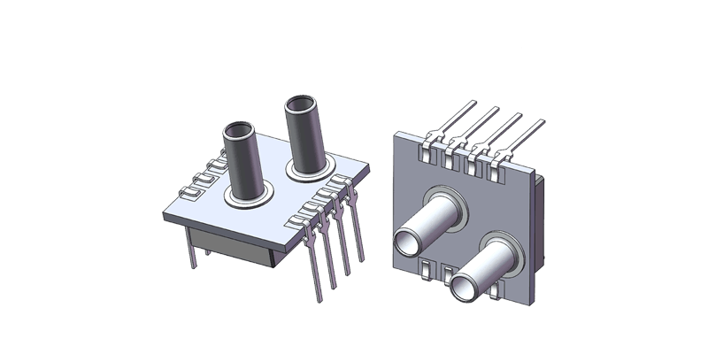
The WF5803F comes in a 4×4 mm LGA package with an optical window on top. In PCB layout, leave an opening above the window, avoid solder mask in that area, and ensure pads are properly metalized for grounding and heat dissipation.
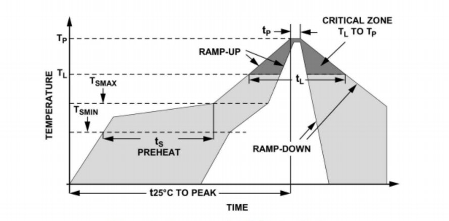
Processus de soudage et profil de température
Use a lead-free reflow profile: ramp-up ≤2℃/s, peak at 245±5℃, dwell above 217℃ for 60 s. For rework, use a 350℃ soldering iron for under 3 s to avoid cracking the window glass.
Alignement optique et protection contre la poussière
Keep the optical window clean during assembly, avoiding solder paste or flux contamination. After soldering, purge with nitrogen or wipe with a lint-free cloth, and adjust the mounting bracket to ensure the laser beam strikes the center of the window perpendicularly.
Processus et outils de test de production de masse
Aperçu du test de workflow
- Vérification unique: Apply known optical or pressure signals on a calibration rig, read digital output, and compare to nominal values.
- Tests environnementaux: Run –20 to 80℃ cycles in a thermal-humidity chamber, record temperature drift and compensation coefficients.
- Vibration & Choc: Conduct 3-axis random vibration tests on a shaker table for vibration immunity; use an impact tester to simulate handling shocks.
Équipement de test recommandé
Plate-forme d'étalonnage de précision: For standard laser power or pressure outputs (e.g. Newport spectrometer, Fluke pressure calibrator).
Chambre environnementale: Programmable temperature-humidity cycling.
Table de vibration / choc: IEC60068 compliant.
Oscilloscope numérique & Analyseur logique: Monitor I²C/SPI timing and electrical characteristics.
Traitement des données en temps réel et optimisation de précision
Algorithmes de filtrage et stratégie d'échantillonnage
Use moving average or exponential smoothing filters combined with dynamic sampling: increase to 1 kHz during high-speed cutting, drop to 100 Hz for static inspection to balance responsiveness and noise suppression.
Température et compensation de dérive
An onboard temperature sensor provides real-time readings. A second-order polynomial model calculates compensation coefficients on-the-fly. No external calibration points are needed to achieve ±0.01%FS stability across the full temperature range.
Étalonnage et autodiagnostic
At power-up, the device performs a self-test by reading built-in calibration parameters and comparing them to reference curves. If deviations exceed limits, it outputs an error code and switches to a safe mode to ensure process safety.
Conclusion
Digital laser sensors deliver core advantages in measurement accuracy, response speed, and system reliability for precision equipment. Taking the WF5803F as an example, its high resolution, low latency, multiple interfaces, and robust environmental immunity strongly support laser cutting, marking, and inspection systems. With proper PCB layout, precise soldering processes, complete mass-production testing, plus real-time filtering and temperature compensation algorithms, equipment developers can rapidly implement efficient, stable sensing solutions and boost product competitiveness.
L’introduction ci-dessus ne fait qu’effleurer la surface des applications de la technologie des capteurs de pression. Nous continuerons à explorer les différents types d’éléments capteurs utilisés dans divers produits, leur fonctionnement ainsi que leurs avantages et inconvénients. Si tu’D Like plus de détails sur ce’Comme discuté ici, vous pouvez consulter le contenu associé plus loin dans ce guide. Si vous êtes pressé par le temps, vous pouvez également cliquer ici pour télécharger les détails de ce guide Données PDF du produit du capteur de pression d'air.
Pour plus d'informations sur d'autres technologies de capteurs, veuillez Visitez notre page de capteurs.