Catalogue
La surveillance de la pression artérielle par montre intelligente repose sur une coordination précise entre une micropompe et un capteur de pression haute résolution. Centré sur le capteur MEMS numérique WF3050D, cet article propose une solution de bout en bout : de l'analyse des exigences, de la sélection du capteur, de l'intégration du système, aux meilleures pratiques d'installation/soudure et aux outils de test de pré-production. L'approche équilibre taille ultra-compacte, faible consommation et haute précision, permettant une évaluation et un déploiement rapides de la faisabilité.
Pour référence seulement
Analyse du contexte de l’application et des exigences
Une fonction de tension artérielle d’une montre intelligente doit contrôler les changements de pression dans un espace minuscule. La micropompe doit contenir moins de 1 cm³ et générer 0 à 50 kPa ; le capteur nécessite une précision de ± 1 % FS, une sortie numérique et une faible dérive (≤ 0,5 % FS/°C), avec courant de veille <10µA et actif <1 mA. Les variations de mouvement et de température au poignet posent des problèmes de stabilité, exigeant un échantillonnage ≥ 200 Hz pour une capture claire de la forme d'onde du pouls. Les ingénieurs doivent équilibrer la configuration, la conception de l'alimentation et l'intégration des algorithmes, tandis que les responsables des achats se concentrent sur la cohérence de l'approvisionnement et le rendement de la production.
1.1 Contraintes d'espace et de puissance
Le module ultra-compact combine une pompe, un tube et un capteur, en prêtant attention à la dissipation thermique et à la résilience aux chocs.
La faible consommation d'énergie globale prolonge la durée de vie de la batterie, correspondant à la capacité de la montre.
1.2 Précision et réactivité
±1%FS répond aux normes de surveillance médicale.
L'échantillonnage ≥200 Hz capture la forme d'onde d'impulsion complète sans crénelage.
1.3 Compatibilité des interfaces
L'interface numérique PDM/I²S du WF3050D réduit la complexité des PCB.
L'intégration rapide du bus avec le MCU simplifie la conception du micrologiciel.
Sélection du capteur et correspondance des paramètres
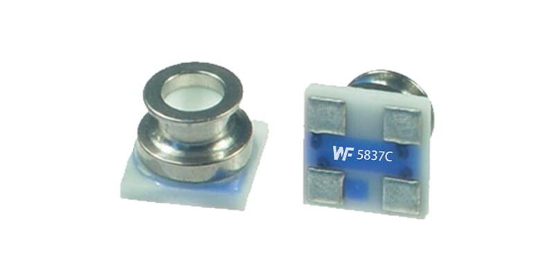
Parmi les capteurs MEMS, le WF3050D se démarque : taille de 3,0 × 5,0 × 0,93 mm, plage de 0 à 50 kPa, I²S/PDM numérique et dérive de 0,48 % FS/°C. La précision typique ≤ ± 0,5 % FS prend en charge le suivi de la pression artérielle jusqu'à 200 mmHg. La tension de fonctionnement de 1,7 à 3,6 V correspond aux rails de montre et aucun CAN externe n'est nécessaire. La conception à port supérieur facilite l'acheminement du gaz ; le couvercle en métal ajoute une résistance aux chocs.
2.1 Portée et précision
0–50 kPa couvre la fenêtre clinique de 95 à 200 mmHg.
Non-linéarité ≤±0,3%FS et répétabilité élevée.
2.2 Comportement thermique
Dérive ≤0,48 %FS/°C, encore améliorée avec une compensation de premier ordre.
Temps de réponse <2 ms pour des changements de pression rapides.
2.3 Ajustement électrique
La sortie numérique directe vers le MCU réduit le bruit et la puissance.
Le démarrage basse tension permet un réveil rapide.

Intégration du système et conception de micropompes
La collaboration efficace entre les capteurs et les pompes s'articule autour du routage du gaz, du support mécanique et de la conception CEM.
Acheminement du gaz: Un tube en silicone court (≤5 mm, Ø1,2 mm) minimise le volume mort.
Montage mécanique: Le support en aluminium avec mousse d'amortissement double couche réduit les vibrations.
Pratiques CEM: Placez les capuchons de filtre et le plan de masse autour des lignes numériques pour réduire le bruit.
Calibrage du micrologiciel: Calibrage automatique du point zéro au démarrage avec compensation de dérive en température.
3.1 Optimisation du chemin du gaz
Le volume de la chambre ≤ 10 µL coupe l'air résiduel.
Le tube à faible adsorption empêche la rétention de gaz.
3.2 Isolation des vibrations & Contrôle thermique
Les coussinets amortisseurs de vibrations réduisent le bruit mécanique.
Le coussin thermique en cuivre sous le capteur favorise l'uniformité de la température.
3.3 Algorithmes du micrologiciel
Calibrage automatique au démarrage, correction continue de la dérive.
L'échantillonnage à grande vitesse avec des filtres numériques équilibre vitesse et stabilité.
Notes d'installation et de soudure
Un placement et une soudure appropriés sont essentiels pour les performances et le rendement.
Orientation: Alignez l’orifice supérieur vers le chemin de la pompe pour éviter tout blocage.
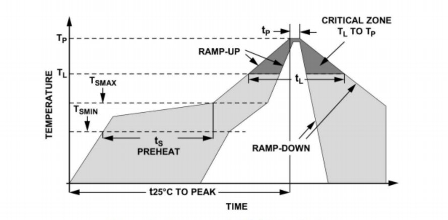
Profil de redistribution: Pic ≤260°C avec 10 à 20 s dans la zone 230 à 260°C.
Pâte à souder: SnAgCu3.0, particules de 45 à 75 µm pour des joints fiables.
Conception de tampons PCB: Grand coussin de terre sous le capteur pour le blindage, périmètre du plan de masse.
Poussière & Protection contre l'humidité: Scellez le port rapidement après la mise en place pour éviter toute contamination.
4.1 Courbe de processus SMT
Préchauffage : 120-150°C → Trempage : 150-180°C → Refusion : 230-260°C → Refroidissement, ≤4°C/s.
Épaisseur de pâte : 100-120 µm.
4.2 Inspection après refusion
AOI vérifie le placement dans une tolérance de 0,1 mm.
Les rayons X confirment les joints de soudure sans vide.
Outils de test et de mesure de pré-production
Avant la production en série, mettez en place des tests en plusieurs étapes pour garantir la cohérence :
Vérification fonctionnelle: Source de gaz calibrée à 0/20/40kPa, enregistrement de l'erreur entre les points.
Stress environnemental: 85°C/85%HR pendant 48h pour évaluer la dérive.
Vibration & Choc: 10–2000 Hz à 5 g pendant 30 min.
Conformité CEM: Immunité rayonnée et conduite selon IEC61000-4.
Équipement:
Banc d'étalonnage de gaz de précision (résolution 0,1Pa).
DAQ haute vitesse (≥2 kHz).
Montages de test automatisés avec manipulation des cartes.
5.1 Flux de travail d'étalonnage
Échauffement 5 min → Appliquer des pressions standard → Enregistrer la sortie → Calculer la linéarité & offset → Générer une courbe d'étalonnage.
5.2 Traçabilité des données
Codage par lots du capteur pour une trace complète.
La journalisation automatisée des données dans MES permet des analyses de qualité.
Conclusion
Ce guide détaille une solution de bout en bout pour intégrer les capteurs de pression MEMS numériques WF3050D dans les systèmes de pression artérielle à micro-pompe de montre intelligente. Couvrant l'analyse des besoins, la sélection des capteurs, l'intégration du système, les meilleures pratiques d'installation et les tests de pré-production, il garantit la miniaturisation, la faible consommation, la précision et la fiabilité, permettant aux équipes d'ingénieurs de déployer en toute confiance les fonctionnalités de pression artérielle hautes performances des montres intelligentes.
L’introduction ci-dessus ne fait qu’effleurer la surface des applications de la technologie des capteurs de pression. Nous continuerons à explorer les différents types d’éléments capteurs utilisés dans divers produits, leur fonctionnement ainsi que leurs avantages et inconvénients. Si tu’D Like plus de détails sur ce’Comme discuté ici, vous pouvez consulter le contenu associé plus loin dans ce guide. Si vous êtes pressé par le temps, vous pouvez également cliquer ici pour télécharger les détails de ce guide Données PDF du produit du capteur de pression d'air.
Pour plus d'informations sur d'autres technologies de capteurs, veuillez Visitez notre page de capteurs.