Catalogar
This article focuses on the selection and application functions of pressure sensors used in smart gas meters. Drawing on the features of the WF5805F 10–500 kPa high-precision digital absolute MEMS sensor, it delves into range matching, sensitivity and resolution, accuracy and stability, and environmental adaptability; analyzes digital interface design and low-power modes; explains integrated packaging, temperature compensation, and reliability requirements; outlines key points for temperature control in installation and soldering, mechanical fixation, moisture protection, and ESD safeguards; and provides practical schemes for gas-source calibration, thermal-chamber testing, signal-integrity checks, and automated data analysis before mass production. Tailored for engineers, procurement managers, and technical decision-makers, it offers actionable solutions to ensure long-term stable and reliable performance under all operating conditions.
1. Sensor Selection Principles
1.1 Range Matching
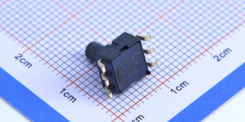
In smart gas meter design, the primary task of the pressure sensor is to accurately measure pipeline gas pressure. Selection must cover both the system’s minimum start-up pressure and its maximum operating pressure. Typical gas-meter operating range is 10 kPa–500 kPa. An absolute-pressure sensor resists atmospheric fluctuations. For example, the WF5805F spans 10 kPa–500 kPa, preventing sensor saturation or dead zones and ensuring full-range measurement integrity.
1.2 Sensitivity and Resolution
Sensitivity determines the sensor’s response to small pressure changes, directly impacting leak alarms and flow integration accuracy. High resolution (e.g., 0.1 kPa) captures subtle pressure variations for real-time warnings. The WF5805F’s piezoresistive MEMS structure with built-in high-performance ADC delivers ≤0.1 kPa resolution, supporting fine-grain metering in smart gas meters.
1.3 Accuracy Class and Long-Term Stability
Smart gas meters demand strict metrological compliance—typically overall linear error <±0.5%FS and drift <0.1%FS per year. Premium MEMS sensors use on-chip temperature compensation and multi-point factory calibration to maintain stable zero and full-scale characteristics from –20 ℃ to 80 ℃.
1.4 Environmental Adaptability
Gas meters often face indoor/outdoor condensation, pipeline vibration, and EMI. Sensor packages should meet IP67 for water-dust protection, employ vibration-damping structures and EMC filtering to block moisture ingress and external noise. In high-altitude or cold-climate deployments, account for air-density effects on absolute-pressure measurements and correct via firmware.
1.5 Vendor Credentials and Consistency
When choosing, evaluate suppliers’ quality-management systems, factory-calibration capabilities, and delivery consistency. Prefer ISO-9001-certified, production-proven manufacturers to guarantee batch uniformity and reliability.
2. Digital Interface & Power Design
2.1 I²C vs. SPI Protocols
Smart-meter MCUs typically read sensors over I²C or SPI. I²C’s two-wire bus saves PCB routing and supports multiple devices; SPI offers higher speeds and stronger noise immunity.
2.2 Low-Power & Wake Modes
Battery-powered meters require sensor quiescent current <50 µA with Sleep/Wake support. The WF5805F maintains µA-level standby current and wakes instantly via external interrupt or timer, extending overall runtime.
2.3 Digital Filtering & Rechazo
To suppress mechanical vibration and power-line noise, add an RC filter before the output or implement digital filtering in the MCU. Proper PCB ground zoning and shielding help meet CE/EMC standards.
2.4 Interface Protection
Field environments may experience surges and ESD. Place TVS diodes and series resistors on I²C/SPI lines to boost surge and ESD robustness, ensuring long-term stability.

3. Functional Integration & Embalaje
3.1 Monolithic Chip Design
High-end MEMS sensors integrate the diaphragm, ASIC front-end, and 12- or 16-bit ADC on one die, significantly cutting external components, saving board space, and reducing cost.
3.2 Temperature Compensation & Factory Calibration
Accurate readings require countering temperature drift. The WF5805F embeds a digital temperature sensor and multi-segment compensation algorithm, completing multi-point calibration at the factory so users need no secondary calibration and achieve ±0.5%FS accuracy out of the box.
3.3 Package Style & Materials
Metal caps or ceramic packages with corrosion-resistant coatings and pressure ports stand up to gas-borne contaminants and deliver <2 ms response, meeting instant-fluctuation sampling needs.
3.4 Reliability & Proceso de dar un título
Before mass production, choose AEC-Q100 automotive-grade packages and conduct thermal cycling, humidity, and vibration tests to ensure over five years of consistent performance, reducing maintenance costs.
4. Installation & Soldering Considerations
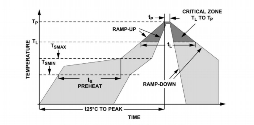
4.1 Reflow Profile Control
Limit peak reflow temperature to ≤260 ℃ for ≤10 s to avoid internal stress that can shift zero point or degrade linearity in the MEMS structure.
4.2 Mechanical Fixation & Vibration Isolation
Avoid applying force to the sensor cap or pressure port during mounting. Use soft adhesives or silicone pads for mechanical isolation to prevent pipeline vibration from transferring to the diaphragm and causing measurement errors.
4.3 Moisture Sealing
After soldering, apply moisture-resistant epoxy or conformal coating around package edges and leads to block trace amounts of water or VOCs in the gas, protecting internal circuits from corrosion or shorts.
4.4 ESD Protection
During handling and assembly, wear wrist straps and use grounded benches and ESD-safe tools to protect the MEMS element from electrostatic damage.
5. Pre-Production Testing & Measurement Plan
5.1 Gas-Source Calibration Bench
Use an adjustable constant-flow gas source and high-precision reference manometer to test linearity and repeatability at 10 kPa, 100 kPa, and 500 kPa, ensuring sensor readings match the standard within ±0.5%FS.
5.2 Thermal-Chamber Cycling
Perform multiple cycles from –20 ℃ to 80 ℃ in a temperature chamber, recording zero and full-scale drift and evaluating the effectiveness of temperature compensation under extreme conditions.
5.3 Signal-Integrity Verification
Employ oscilloscopes and logic analyzers to monitor I²C/SPI rise/fall times and bus noise, verifying timing compliance and stable, packet-loss-free communication.
5.4 Automated Data Analysis
Leverage test-automation software to collect batch data, apply statistical methods (mean, standard deviation, offset), set pass/fail criteria, and generate reports to guide shipping decisions.
Conclusión
For engineers and procurement managers, selecting and applying pressure sensors in smart gas meters requires balancing range, sensitivity, accuracy, digital interfaces, and environmental resilience. The WF5805F exemplifies a high-precision digital absolute MEMS device with full-range coverage, on-chip compensation, and integrated packaging that delivers stable, reliable metering. Coupled with controlled installation and soldering processes and rigorous pre-production testing, it ensures consistent, high-performance operation over the product lifecycle.
La introducción anterior sólo toca la superficie de las aplicaciones de la tecnología de sensores de presión. Continuaremos explorando los diferentes tipos de elementos sensores utilizados en diversos productos, cómo funcionan y sus ventajas y desventajas. Si desea obtener más detalles sobre lo que se analiza aquí, puede consultar el contenido relacionado más adelante en esta guía. Si tiene poco tiempo, también puede hacer clic aquí para descargar los detalles de estas guías. Producto del sensor de presión de aire datos PDF.
Para obtener más información sobre otras tecnologías de sensores, por favor Visite nuestra página de sensores.