Catalogar
En cirugía mínimamente invasiva, el control y la monitorización de la presión del insuflador son fundamentales para la seguridad del paciente y una visualización operativa óptima. Seleccionar el sensor de presión adecuado implica equilibrar la medición de alta precisión, la respuesta dinámica rápida y la estabilidad duradera. Este artículo proporciona un análisis exhaustivo de los materiales de los sensores barométricos MEMS, los métodos de embalaje y los procesos de fabricación, y cubre los requisitos funcionales, los parámetros críticos, las mejores prácticas de instalación y soldadura, los flujos de trabajo de pruebas de preproducción y las estrategias de validación de seguridad y confiabilidad. Dirigido a ingenieros y compradores técnicos, ofrece un enfoque sistemático para determinar la solución ideal de sensor de presión analógico WF100E en entornos clínicos y regulatorios rigurosos, garantizando la integridad del rendimiento del dispositivo incluso después de un uso y esterilización extensivos.
Requisitos de rendimiento detallados
1.1 Estándares de precisión y linealidad
Los insufladores requieren sensores con una precisión superior a ±0,5% FS para controlar estrictamente la discrepancia entre las presiones intraabdominales mostradas y reales. La alta linealidad garantiza una respuesta proporcional en todo el rango de medición, lo que reduce la complejidad de la calibración y mejora la confiabilidad del sistema.
1.2 Sensibilidad y capacidad de respuesta dinámica
Los cambios rápidos de presión causados por la manipulación de tejidos u oclusiones de los tubos exigen una respuesta a nivel de milisegundos y una resolución de alta presión. Las microestructuras MEMS, a través de dimensiones de diafragma minimizadas y microcanales optimizados, logran una detección rápida de variaciones sutiles de presión, salvaguardando el procedimiento quirúrgico.
1.3 Estabilidad y durabilidad a largo plazo
Los ciclos de presión repetidos y la esterilización desafían la longevidad del sensor. Los sensores MEMS de primera calidad que utilizan silicio o cerámica de baja expansión combinados con sellado de soldadura completa o soldadura láser mantienen una desviación cero por debajo de ±0,1% FS con el tiempo, lo que garantiza un rendimiento uniforme durante todo el ciclo de vida del dispositivo médico.
1.4 Comparación de materiales y técnicas de embalaje
- Opciones de diafragma: El silicio ofrece una sensibilidad ultraalta, mientras que el acero inoxidable destaca por su robustez mecánica.
- Métodos de sellado: Los sustratos cerámicos con soldadura láser ofrecen una resistencia superior a la corrosión; Las carcasas metálicas totalmente soldadas proporcionan máxima protección estructural y blindaje EMI.
- Prevención de fugas: Los conjuntos de juntas tóricas y juntas metálicas compuestas bloquean la entrada de fluidos y agentes de esterilización.

Parámetros de selección crítica explicados
2.1 Coincidencia de rango y margen de seguridad
Con presiones clínicas de hasta 20 kPa, seleccione un rango de sensor de aproximadamente 25 kPa para incluir al menos un margen de seguridad del 20 %, evitando la sobrecarga del elemento y preservando la linealidad a escala completa.
2.2 Resolución e incremento mínimo detectable
Se necesita una resolución de 0,1 kPa o mejor para realizar ajustes precisos de la presión, lo que proporciona datos detallados para controlar los algoritmos para una insuflación precisa.
2.3 Compensación de temperatura y tolerancia ambiental
Los circuitos de compensación incorporados limitan la deriva térmica a ±0,01 % FS/℃ entre 20 ℃ y 40 ℃, manteniendo la estabilidad frente a las variaciones ambientales que se encuentran comúnmente en los quirófanos.
2.4 Estándares de resistencia a interferencias y EMC
Los entornos médicos están plagados de fuentes de ruido electromagnético; Los sensores deben incorporar blindaje EMI, filtrado de entrada y salidas diferenciales, junto con prácticas de diseño y conexión a tierra de PCB para garantizar mediciones repetibles y con bajo nivel de ruido.
Las mejores prácticas de instalación y soldadura
3.1 Ubicación óptima y configuración de los tubos
Monte el sensor cerca de la entrada de gas para minimizar las distorsiones inducidas por los tubos. Asegure curvas graduales y evite ángulos agudos para evitar turbulencias de flujo y lecturas erróneas.
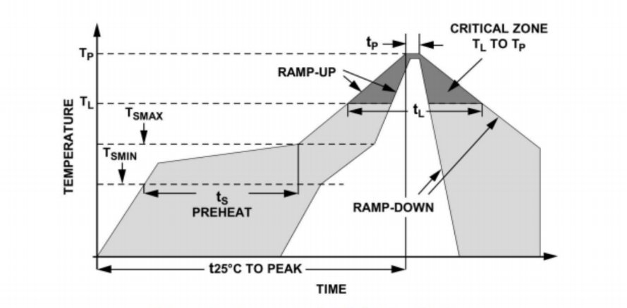
3.2 Temperaturas de soldadura controladas y exposición a la humedad
Utilice aleaciones de soldadura de baja temperatura (punto de fusión ≤ 250 ℃) y técnicas de reflujo escalonado para evitar la degradación del adhesivo interno. Controle la humedad durante la soldadura para evitar la absorción de humedad por parte de componentes sensibles.
3.3 Estrategias de protección contra el estrés del plomo
Realice pruebas de tracción posteriores a la soldadura en los cables y luego refuerce las uniones con compuestos de silicona o epoxi para distribuir las tensiones mecánicas y evitar fallas por fatiga durante el transporte y el uso.
3.4 Procedimientos de sellado y blindaje eléctrico
Aplique recubrimientos conformados a las conexiones eléctricas, integre blindajes con conexión a tierra y realice un encapsulado final para aislar completamente los circuitos internos de los ambientes externos, elevando la clasificación de protección a IP67 o superior.
Protocolos de prueba de preproducción y herramientas
4.1 Equipo de referencia y calibración multipunto
Implemente equipos de calibración de presión automatizados o probadores de peso muerto para calibración cero, media escala y escala completa. Genere conjuntos de datos de calibración estadística para verificar la consistencia de los lotes y la distribución de precisión.
4.2 Perfiles de características de salida y métricas de error
Utilice sistemas DAQ de precisión y plantillas personalizadas para realizar barridos de presión, capturando histéresis y repetibilidad. Calcule métricas como no linealidad, histéresis y precisión de repetición para confirmar el rendimiento dentro de los límites de ±0,5 %FS.
4.3 Envejecimiento ambiental y pruebas de vida acelerada
Someta las unidades a ciclos de 85 ℃/85 % HR y perfiles de vibración para simular el uso a largo plazo. Mida la deriva en la compensación cero y la sensibilidad después del envejecimiento para modelar el rendimiento de la vida útil en el mundo real.
4.4 Integración de automatización y instrumentos de laboratorio esenciales
Equipar las instalaciones con multímetros digitales de alta resolución, circuitos puente de Wheatstone, cámaras climáticas y plataformas de prueba controladas por PLC/PC. Implemente software para la adquisición y el análisis de datos en tiempo real y la clasificación automatizada de pasa/falla.
Validación integral de seguridad y confiabilidad
5.1 Diseño redundante de detección y a prueba de fallos
Integre sensores duales o múltiples con lógica de votación para redundancia de datos; En caso de falla del sensor primario, cambie a canales de respaldo y emita alertas, manteniendo un monitoreo de presión ininterrumpido.
5.2 Análisis de fatiga y ciclado a largo plazo
Ejecute miles de ciclos de presión en condiciones clínicas simuladas, monitoreando la deriva de los parámetros y las desviaciones inducidas por la fatiga para informar los programas de mantenimiento y los intervalos de servicio.
5.3 Tolerancia a sobrecargas y pruebas de impacto
Realice pruebas de sobrecarga estática a 1,5–2×FS y choque multieje según IEC 60068-2-27 para verificar la resiliencia del diafragma y la integridad del paquete bajo cargas extremas.
5.4 Cumplimiento Normativo y Certificación Médica
Cumpla con los requisitos de gestión de calidad ISO 13485 y recopile documentos de verificación de diseño, evaluación de riesgos y biocompatibilidad para el marcado CE y la autorización de la FDA, asegurando una alineación regulatoria completa.
Conclusión
Esta guía ofrece una metodología exhaustiva para seleccionar el sensor de presión MEMS analógico WF100E para insufladores médicos, que cubre opciones de materiales avanzadas, métricas de rendimiento de precisión, procesos de instalación y soldadura refinados, pruebas rigurosas de preproducción y una estricta validación de seguridad. El empleo de estas mejores prácticas garantiza que los insufladores proporcionen un control de presión preciso, confiable y seguro, lo que en última instancia respalda el éxito de las cirugías mínimamente invasivas y el bienestar del paciente.
La introducción anterior sólo toca la superficie de las aplicaciones de la tecnología de sensores de presión. Continuaremos explorando los diferentes tipos de elementos sensores utilizados en diversos productos, cómo funcionan y sus ventajas y desventajas. Si desea obtener más detalles sobre lo que se analiza aquí, puede consultar el contenido relacionado más adelante en esta guía. Si tiene poco tiempo, también puede hacer clic aquí para descargar los detalles de estas guías. Producto del sensor de presión de aire datos PDF.
Para obtener más información sobre otras tecnologías de sensores, por favor Visite nuestra página de sensores.