Catalogar
El control de la presión arterial mediante un reloj inteligente se basa en una coordinación precisa entre una microbomba y un sensor de presión de alta resolución. Centrado en el sensor MEMS digital WF3050D, este artículo ofrece una solución integral: desde análisis de requisitos, selección de sensores, integración de sistemas hasta mejores prácticas de instalación/soldadura y herramientas de prueba de preproducción. El enfoque equilibra el tamaño ultracompacto, el bajo consumo de energía y la alta precisión, lo que permite una rápida evaluación e implementación de la viabilidad.
Solo como referencia
Análisis de antecedentes y requisitos de la aplicación
La función de presión arterial de un reloj inteligente debe controlar los cambios de presión en un espacio reducido. La microbomba debe caber por debajo de 1 cm³ y generar entre 0 y 50 kPa; El sensor requiere una precisión de ±1 %FS, salida digital y baja deriva (≤0,5 %FS/°C), con corriente de reserva. <10 µA y activo <1 mA. La variación de movimiento y temperatura en la muñeca plantea desafíos de estabilidad y exige un muestreo de ≥200 Hz para una captura clara de la forma de onda del pulso. Los ingenieros deben equilibrar el diseño, el diseño energético y la integración de algoritmos, mientras que los gerentes de adquisiciones se centran en la coherencia del suministro y el rendimiento de la producción.
1.1 Restricciones de espacio y energía
El módulo ultracompacto combina bomba, tubería y sensor, prestando atención a la disipación de calor y la resistencia a los golpes.
El bajo consumo de energía general prolonga la vida útil de la batería, igualando la capacidad del reloj.
1.2 Precisión y capacidad de respuesta
±1%FS cumple con los estándares de monitoreo médico.
El muestreo de ≥200 Hz captura la forma de onda de pulso completa sin alias.
1.3 Compatibilidad de interfaz
La interfaz digital PDM/I²S del WF3050D reduce la complejidad de la PCB.
La rápida integración del bus con MCU simplifica el diseño del firmware.
Selección del sensor y coincidencia de parámetros
Entre los sensores MEMS, destaca el WF3050D: tamaño de 3,0×5,0×0,93 mm, rango de 0 a 50 kPa, I²S/PDM digital y deriva de 0,48% FS/°C. La precisión típica ≤±0,5% FS admite el seguimiento de la presión arterial hasta 200 mmHg. El voltaje de funcionamiento de 1,7 a 3,6 V coincide con los rieles de vigilancia y no se necesita un ADC externo. El diseño del puerto superior facilita el enrutamiento del gas; La tapa de metal añade resistencia al impacto.
2.1 Alcance y Precisión
0–50 kPa cubre una ventana clínica de 95 a 200 mmHg.
No linealidad ≤±0,3%FS y alta repetibilidad.
2.2 Comportamiento Térmico
Deriva ≤0,48 %FS/°C, mejorada aún más con compensación de primer orden.
Tiempo de respuesta <2 ms para cambios rápidos de presión.
2.3 Ajuste eléctrico
La salida digital directa a MCU reduce el ruido y la potencia.
El arranque de bajo voltaje permite un despertar rápido.

Integración del sistema y diseño de micro bomba
Colaboración efectiva entre sensores y bombas en el enrutamiento de gas, soporte mecánico y diseño EMC.
Enrutamiento de gas: El tubo de silicona corto (≤5 mm, Ø1,2 mm) minimiza el volumen muerto.
Montaje mecánico: El soporte de aluminio con espuma amortiguadora de doble capa reduce la vibración.
Prácticas de EMC: Coloque tapas de filtro y un plano de tierra alrededor de las líneas digitales para reducir el ruido.
Calibración de firmware: Calibración automática del punto cero al inicio con compensación de deriva de temperatura.
3.1 Optimización de la ruta del gas
El volumen de la cámara ≤10 µL reduce el aire residual.
Los tubos de baja adsorción evitan la retención de gas.
3.2 Aislamiento de vibraciones & Control Térmico
Las almohadillas amortiguadoras de vibraciones reducen el ruido mecánico.
La almohadilla térmica de cobre debajo del sensor fomenta la uniformidad de la temperatura.
3.3 Algoritmos de firmware
Autocalibración de inicio, corrección continua de deriva.
El muestreo de alta velocidad con filtros digitales equilibra la velocidad y la estabilidad.
Notas de instalación y soldadura
La colocación y soldadura adecuadas son fundamentales para el rendimiento y el rendimiento.
Orientación: Alinee el puerto superior hacia la trayectoria de la bomba para evitar obstrucciones.
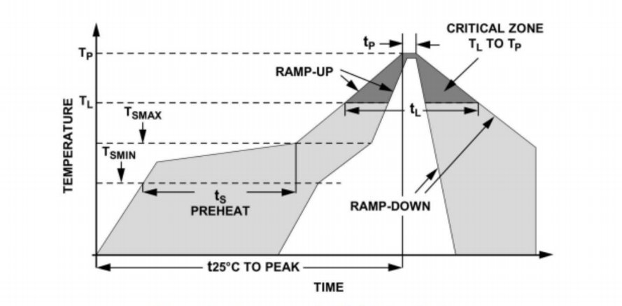
Perfil de reflujo: Pico ≤260°C con 10–20s en la zona de 230–260°C.
Pasta de soldadura: SnAgCu3.0, partículas de 45–75 µm para uniones confiables.
Diseño de almohadilla de PCB: Almohadilla de tierra grande debajo del sensor para blindaje, perímetro del plano de tierra.
Polvo & Protección por humedad: Selle el puerto inmediatamente después de la colocación para evitar la contaminación.
4.1 Curva del proceso SMT
Precalentar: 120–150°C → Remojo: 150–180°C → Reflujo: 230–260°C → Enfriar, ≤4°C/s.
Espesor de la pasta: 100–120 µm.
4.2 Inspección posterior al reflujo
AOI comprueba la colocación dentro de una tolerancia de 0,1 mm.
Los rayos X confirman uniones de soldadura sin huecos.
Herramientas de pruebas de preproducción y medición
Antes de la producción en masa, configure pruebas de varias etapas para garantizar la coherencia:
Cheque funcional: Fuente de gas calibrada a 0/20/40 kPa, error de registro en todos los puntos.
Estrés ambiental: 85°C/85%RH durante 48h para evaluar la deriva.
Vibración & Choque: 10–2000 Hz a 5 g durante 30 min.
Cumplimiento de EMC: Inmunidad radiada y conducida según IEC61000-4.
Equipo:
Banco de calibración de gases de precisión (resolución 0,1Pa).
DAQ de alta velocidad (≥2kHz).
Dispositivos de prueba automatizados con manejo de tableros.
5.1 Flujo de trabajo de calibración
Calentamiento 5min → Aplicar presiones estándar → Registro de salida → Linealidad de cálculo & offset → Generar curva de calibración.
5.2 Trazabilidad de datos
Codificación por lotes de sensores para seguimiento completo.
El registro de datos automatizado en MES permite realizar análisis de calidad.
Conclusión
Esta guía detalla una solución integral para integrar sensores de presión MEMS digitales WF3050D en sistemas de presión arterial con microbomba de reloj inteligente. Cubriendo análisis de requisitos, selección de sensores, integración de sistemas, mejores prácticas de instalación y pruebas de preproducción, garantiza miniaturización, bajo consumo, precisión y confiabilidad, lo que permite a los equipos de ingenieros implementar funciones de presión arterial de reloj inteligente de alto rendimiento con confianza.
La introducción anterior sólo toca la superficie de las aplicaciones de la tecnología de sensores de presión. Continuaremos explorando los diferentes tipos de elementos sensores utilizados en diversos productos, cómo funcionan y sus ventajas y desventajas. Si desea obtener más detalles sobre lo que se analiza aquí, puede consultar el contenido relacionado más adelante en esta guía. Si tiene poco tiempo, también puede hacer clic aquí para descargar los detalles de estas guías. Producto del sensor de presión de aire datos PDF.
Para obtener más información sobre otras tecnologías de sensores, por favor Visite nuestra página de sensores.


