Katalog
This article presents an end-to-end solution for integrating the WF183DE digital MEMS pressure sensor into an emergency starter power-bank air pump—featuring four inflation modes (basketball, bicycle, motorcycle, car), auto-stop intelligence, multi-unit switching, built-in lighting, and comprehensive safety protections. We cover requirements analysis, hardware selection, mounting and soldering best practices, pre-production testing workflows and tools, as well as firmware and system integration, providing engineers, purchasing managers, and technical decision-makers with a clear, reliable guide to ensure precision, stability, and superior user experience.
System Requirements & Sensor Role
1.1 Functional Overview
Safety Assurance: Monitors and replenishes tire pressure to prevent roadside hazards.
Multi-mode Support: Four presets (basketball, bicycle, motorcycle, car) cover pressures from ~8 PSI to 150 PSI.
Auto-Stop: Over-pressure and deflation thresholds trigger pump shutoff when target pressure is reached.
Unit Switching: PSI, BAR, KPA options for user preference.
Illumination: Integrated LED for low-light operation.
Full-Auto & Protection: Over-temp, over-current, low-voltage shutdown, and auto-activation via pressure trigger.
1.2 Sensor Capabilities
Accuracy: ±1 %FS covers entire 0–150 PSI range.
Digital Interface: PDM or I²C/SPI output for robust MCU communication.
Geringe Leistung: µA-level consumption extends battery life.
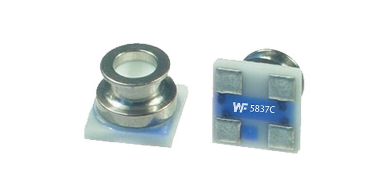
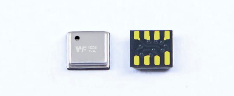
Compact: 3 × 3 mm LGA footprint fits tight pump housings.
1.3 Solution Mapping
Map four modes to pressure setpoints (e.g., basketball (~8 PSI), bicycle (0–60 PSI), motorcycle (0–80 PSI), and car (0–150 PSI). The WF183DE’s 0–150 PSI range easily maps to these modes with firmware thresholds and auto-mode switching ).
Implement auto-stop via firmware interrupts on threshold reached.
Integrate unit conversion in MCU for real-time display.
Mounting & Lötrichtlinien
2.1 PCB Layout
Top-port Alignment: Ensure the sensor’s sampling port faces the pump’s air channel unobstructed.
Clearance: ≥0.5 mm around the port to prevent solder bridging.
Thermal Isolation: Avoid large copper pours beneath to minimize thermal drift.
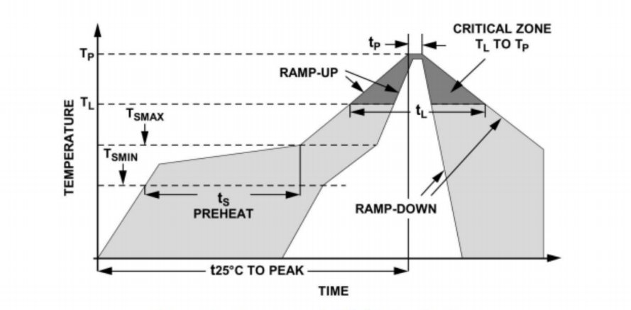
2.2 Reflow Profile
Peak ≤ 260 ℃, ramp ≤ 2 ℃/s, 30–60 s above liquidus per JEDEC J-STD-020.
Controlled solder paste volume via fine-mesh stencil.
Use appropriate flux to avoid port clogging.
2.3 Protective Measures
Apply silicone dot sealing around edges, leaving ports clear.
Black-coat inner walls to prevent light interference if co-locating with optics.
Tests vor der Produktion & Werkzeuge
3.1 First Article Inspection
Pressure Calibrator (e.g., I2C Digital Pressure sensor test module): five-point linearity and accuracy checks.
Thermal Chamber: −20 ℃, 25 ℃, 85 ℃ cycles for drift evaluation.
Vibration/Shock: ISO 16750-3 for automotive-grade durability.
3.2 Production-Line QA
Flying Probe: pin-continuity and impedance check.
Leak Test: ≤ 1×10⁻⁶ mbar·L/s via automated fixtures.
Functional Fixture: embedded pump and air source with MES-linked pass/fail logs for setpoint, unit switch, auto-stop validation.
3.2 wave filter
To balance responsiveness and stability, a simple IIR or moving-average filter is applied to sensor data to suppress noise without compromising real-time feedback
Firmware & Systemintegration
4.1 Firmware Essentials
Interrupt-driven threshold detection for fast pump shutoff.
Filtering: IIR or moving-average to balance responsiveness and stability.
Self-Test: On-power read of sensor ID and health registers.
4.2 User Interface
Real-time display of current vs. target pressure and fill percentage.
Button/rotary selector for mode and unit change with audible feedback.
Auto backlight on low-light detection.
Zuverlässigkeit & Einhaltung
5.1 Burn-in & Aging
- 168 h at 85 %RH/85 ℃, monitor drift < ±2 %FS and motor performance.
5.2 Regulatory & Sicherheit
EMV: IEC 61000-4-2/-4-3 ESD and radiated immunity.
Sicherheit: UL 62368-1 for insulation and over-current protection in the power module.
Abschluss
By systematically addressing sensor selection, PCB design, soldering, validation testing, firmware, UI, and compliance, this guide delivers a turnkey solution for integrating the WF183DE digital pressure sensor into an emergency air-pump module—ensuring high precision, robust performance, and end-user safety.
Die obige Einführung kratzt nur an der Oberfläche der Anwendungen der Drucksensortechnologie. Wir werden weiterhin die verschiedenen Arten von Sensorelementen untersuchen, die in verschiedenen Produkten verwendet werden, wie sie funktionieren und welche Vor- und Nachteile sie haben. Wenn Sie detailliertere Informationen zu den hier besprochenen Themen wünschen, können Sie sich die entsprechenden Inhalte weiter unten in diesem Handbuch ansehen. Wenn Sie unter Zeitdruck stehen, können Sie auch hier klicken, um die Details dieser Leitfäden herunterzuladen PDF -Daten des Luftdrucksensorprodukts.
Weitere Informationen zu anderen Sensortechnologien finden Sie hier Besuchen Sie unsere Sensors -Seite.