- Podle WFsensors
Keeping a sensor’s output predictable and repeatable across the whole temperature range matters in many industrial and medical setups. Starting from a constant-voltage drive, the write-up explains how power supply and compensation network work together to curb temperature-driven zero and sensitivity drift. Drawing on the physics of silicon piezoresistive sensors a micro-differential chips, it lays out practical steps for different ranges (10 mBar to 7 Bar) and temperatures, and suggests manufacturable packaging and calibration flows.
Katalog
1. Constant-voltage drive principle and full-range compensation design
A constant-voltage drive is more than just a fixed voltage. For silicon piezoresistive sensors, a steady drive cuts self-heating and power-supply noise that would otherwise taint measurements. Using a 5V constant source for typical SMD or DIP-packaged silicon sensors keeps sensitivity up while limiting thermal effects. The drive must handle both transient response and long-term drift — so design in low-noise regulation, soft-start and filter networks. Full-range compensation doesn’t erase temperature coefficients; it aligns the sensor body and external compensation so the device stays stable within a given compensation band (recommended −10°C to 60°C). Practically, place the micro-differential sensing chip and a thick-film thermistor on the same ceramic base so local thermal coupling lines up chip behaviour with the compensation point, cutting zero and sensitivity drift. The drive supply should offer tiny ripple (for very low-level measurements <10 µV) and be used with differential readout to maximise signal-to-noise.
Drive stability and noise control
Key drive points: low output impedance, quick suppression of supply transients, and matched filtering. For low-range devices (10 mBar class), even minute power noise converts to measurable pressure error. So use a front-end differential amplifier, add RC low-pass filtering on the constant-voltage output, and include common-mode rejection. Keep PCB layout tight with short loops and low-impedance grounding. Use a precision reference and differential ADC, and add software filtering (e.g. Kalman or median filters) to boost repeatability and stability.

2. Implementation of silicon piezoresistive technology in precision measurement
Silicon piezoresistive sensors change resistance with strain; that change becomes the voltage we read. For high-accuracy work, the crucial items are bridge balance, amplifier noise and thermal coupling. Micro-differential chips made in diffusion silicon give high sensitivity and good linearity but are more temperature- and stress-sensitive. So system design must deal with material matching, stress relief and packaging techniques. Choose matched bridge resistors, low-drift amplifiers and adjustable gain stages so both small-range (breathing-monitor) and large-range (liquid-flow) applications behave reliably. OEM pressure sensors should undergo multi-point temperature and pressure calibration before shipment and store correction coefficients for field use.
Micro-differential chip and zero-offset stability strategy
Zero-offset drift usually comes from internal stress and temperature gradients. Placing a thick-film thermistor on the ceramic base and performing precise laser trimming aligns the compensation curve to the device zero. On the production line, thermal cycling followed by laser micro-adjustment significantly reduces batch zero variance. Pairing differential readout with hardware/software calibration keeps bidirectional (positive/negative) sensors symmetric in response, which is vital for testing prototypes and for production consistency.
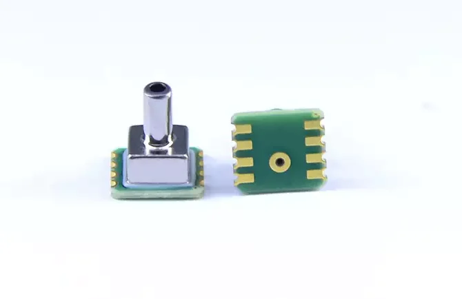
3. Packaging and process points: DIP vs SMD trade-offs
Packaging affects thermal behaviour and mechanical stress directly. Dual in-line packages (DIP) are handy for lab work and easy mounting; ceramic bases offer steady thermal paths and make integrating thick-film compensation simple. SMD saves space and suits automated assembly. The SRT3100 series, for example, uses DIP to mount the compensated micro-differential chip, ceramic base and thick-film thermistor on a PCB — this eases integration and batch calibration. Pack design must also handle potting material, sealing and lead stress management to avoid package-induced measurement errors.
Ceramic base and thick-film compensation network
Integrating a thick-film thermistor onto a ceramic base is a practical way to compensate for temperature. Thermistor placement, resistance curve and laser-trim strategy together determine compensation accuracy. Thick-film materials must match the silicon chip’s temperature behaviour; laser trimming on the line lets you tune each device so compensation meets spec across −10°C to 60°C. Because ceramic conducts heat well, you get stable thermal coupling and therefore effective compensation.
4. Temperature compensation workflow and calibration methods
Effective compensation works on three levels: device, package and system. Device-level control relies on silicon geometry and process to reduce temp coefficients; package-level uses thick-film thermistors and ceramic bases for body compensation; system-level applies software-based linear or non-linear corrections from multi-point calibration data. I recommend at least three temperature points (low, mid, high) plus multiple pressure points at each temperature, record correction coefficients and program them into the device ID or supply a calibration sheet. Digital types (model code with “D”) can store calibration curves in firmware; analogue types (with “S”) should include hardware trim options and be paired with system filtering.
Laser trimming and batch consistency control
Laser trimming is used to fine-tune thick-film thermistor values, matching zero and compensation points precisely. Run automated test fixtures to map each device’s temperature response, then selectively laser-trim the thick-film resistor to bring it into spec. Combine this with statistical process control (SPC) and traceable testing to ensure batch consistency and traceability, cutting field variability tied to temperature.
5. Application-integration tips
At system level, focus on power, mechanical mounting, installation location and software filtering. Use a stable 5V constant-voltage source (or the device’s recommended value) and leave room in the design for a differential amplifier and anti-interference filtering ahead of the ADC. In mounting, avoid heat spots and stress concentrations — give the sensor thermal isolation or balancing and keep it away from local heat sources. For liquid-flow and liquid-level sensing, think about media compatibility, long-term immersion effects and sealing strategies. For bidirectional pressure measurement, pick a model that supports it and apply symmetric calibration in the system.
Drive-voltage recommendations and test methods
A 5V constant-voltage supply is the default recommendation; verify how different drive points affect sensitivity and self-heating during prototype testing. Test routines should include static-drift, temperature-cycling and shock/vibration tests. Use a high-precision differential ADC to log data and implement multi-stage filtering plus fault detection in firmware. Ship a calibration report stating the temperature compensation band and limits so the end system can do sensible error handling.
Závěr
A constant-voltage drive is central to achieving full-range temperature compensation and precision measurement, but it must be tightly integrated with sensor design, packaging and calibration. Mounting the thick-film thermistor on a ceramic base and laser-trimming the compensation network, together with a low-noise constant-voltage supply and differential readout, gives stable, repeatable output across the −10°C to 60°C compensation range for OEM pressure sensors. In system integration, pay attention to drive stability, package stress and batch consistency to keep silicon piezoresistive sensors reliable over the long run.
Výše uvedený úvod pouze poškrábe povrch aplikací technologie tlakových senzorů. Budeme pokračovat ve zkoumání různých typů senzorových prvků používaných v různých produktech, jejich fungování a jejich výhod a nevýhod. Pokud byste chtěli více podrobností o tom, o čem se zde diskutuje, můžete se podívat na související obsah později v této příručce. Pokud vás tlačí čas, můžete také kliknout sem a stáhnout si podrobnosti o těchto příručkách Data produktu PDF na tlak vzduchu.
Pro více informací o dalších senzorových technologiích prosím Navštivte naši stránku Sensors.