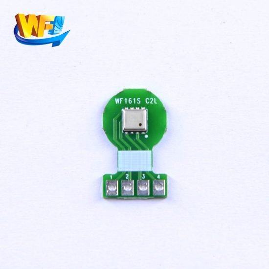
Tire pressure sensors turn mechanical pressure into stable electrical signals, monitoring and controlling an inflator’s start and stop in real time to prevent over- or under-inflation. This piece looks at principles, system integration, reliability, low-power design and calibration from five angles, offering engineers practical technical analysis and highlighting the roles and trade-offs of digital pressure sensors, absolute pressure sensors and analogue sensors in inflation scenarios.
Catalog
1. Function and operating principle
A tyre pressure sensor converts pressure into an electrical signal when the sensing diaphragm is deflected. Digital absolute pressure sensors include an ADC and compensation algorithms, outputting I²C/SPI digital data that the controller can read to control the inflator’s start/stop. Analogue sensors remain useful in cost-sensitive or legacy systems; their output is amplified and filtered before MCU sampling. Digital pressure sensors and low-power sensors are especially important in battery-powered and vehicle environments.
1.1 Detailed operating mechanism
The diaphragm bends under absolute pressure, causing resistive or capacitive changes which the signal conditioning circuitry converts into a voltage or digital reading. Digital absolute pressure sensors typically integrate temperature compensation and calibration curves to reduce zero-offset drift and temperature effects. Analogue sensors rely on external amplifiers and a high-precision reference to recover and linearise the signal, ensuring the inflator control receives accurate commands.

2. System integration and signal path
In an inflator system, the sensor should sit close to the pressure source to cut response time. Sensor output is filtered and compensated before reaching the control unit. With digital sensors you can read temperature-compensated absolute pressure directly; with analogue sensors you must design a high-precision ADC and reference. Communication links, grounding and EMI protection directly affect measurement stability and the reliability of inflator control.
2.1 Layout and wiring requirements
You must optimise the distance, shielding and ground return between sensor and controller to avoid noise injection. Digital interfaces (I²C/SPI) reduce the need for external analogue conditioning, but you still need to consider bus robustness and timing integrity. For analogue paths, plan short PCB traces, a stable reference and differential amplification so readings stay steady during inflator start/stop transients.
2.2 Technical requirements and challenges for differential pressure detection
Both differential and absolute pressure measurements can appear in inflation systems; differential measurement demands higher resolution and zero-point stability. The sensor must use precise calibration and temperature compensation to keep non-linearity and hysteresis minimal, so small changes in the measurement range still provide reliable control signals and avoid small over- or under-pressure hazards.
3. Reliability and safety protection design
To keep the inflation process safe, the system needs layered protections: sensor fault detection, redundant thresholds and over-pressure shutoff. If a sensor’s output distorts or goes open, the controller should enter a safe stop or degraded mode. Choose absolute pressure sensors with low long-term drift and high shock/vibration resistance, and use moisture-resistant packaging and stress-relief on the silicon die to improve reliability in vehicle environments.
3.1 Fault detection and redundancy strategies
Implement self-tests, cross-checks with multiple measurements and over-limit protection logic so, on sensor failure, a backup algorithm or manual warning is triggered. Hardware features such as fuses, current limiting and EMC isolation plus software filtering and anomaly detection mean the inflator will enter a safe state if a sensor shorts or falsely alarms.
4. Low-power operation and response optimisation
For portable and vehicle power constraints, low-power sensors and sleep/wake strategies are essential. Digital absolute pressure sensors can run in low-power modes with fast wake-up, cutting system energy use while keeping responsiveness. At system level, manage sample rates, use event-triggered measurements and local filtering to reduce MCU load, balancing measurement accuracy with power consumption.
4.1 Power management and wake strategy
Wake the controller with hardware interrupts or event detection and only raise the sampling rate when needed to greatly reduce average power. Using digital pressure sensors offloads temperature compensation and calibration, lowering MCU computation. In portable units, low-power modes and batch sampling extend battery life without sacrificing inflation accuracy.
5. Calibration, testing and maintenance
Accurate inflation depends on a reliable calibration sequence: zero-point calibration, temperature compensation and span calibration. Perform batch consistency tests before production and offer a quick on-site self-check to detect sensor offset. Maintenance should include regular self-test logs, anomaly alerts and traceable calibration records so the inflator keeps within permitted accuracy and safety margins over time.
5.1 Calibration process and test points
During factory calibration, record calibration coefficients across multiple temperature points and provide device-side quick calibration commands for field verification. Testing should cover full range extremes, temperature drift, hysteresis and shock/vibration response. Batch trace data lets engineers spot long-term drift and schedule return or field recalibration to maintain inflation accuracy.
Conclusion
Applying digital pressure sensors, absolute pressure sensors and low-power sensors appropriately in an inflator system delivers high-accuracy pressure feedback and safe control. When choosing components, balance digital vs analogue interfaces, power consumption, response and reliability. Combine that with proper system integration and calibration processes to significantly improve inflation accuracy and safety, reducing incidents and customer complaints.
The above introduction only scratches the surface of the applications of pressure sensor technology. We will continue to explore the different types of sensor elements used in various products, how they work, and their advantages and disadvantages. If you’d like more detail on what’s discussed here, you can check out the related content later in this guide. If you are pressed for time, you can also click here to download the details of this guides air pressure sensor product PDF data.
For more information on other sensor technologies, please visit our sensors page.
