Programmatic linear compensation and sensor hardware compensation are two core approaches to dealing with sensor signal errors. Let’s break down the differences in detail.
In plain terms:
Sensor hardware compensation is done at the physical level — extra hardware components or a dedicated chip correct the raw signal inside the sensor or on the PCB. Think of it as “fixing the problem before the signal is digitised.”
Programmatic linear compensation (software compensation) is done at the digital level — an algorithm running on a microcontroller (MCU) corrects the digitised signal mathematically. That’s “fixing the problem after the signal has been digitised.”
Below is a side-by-side comparison across multiple dimensions.
| Dimension | Sensor hardware compensation | Programmatic linear compensation (software compensation) |
|---|---|---|
| Essence | Physical circuit correction | Mathematical model correction |
| Implementation location | Inside the sensor or in the nearby signal-conditioning circuit | Software running on a microcontroller (MCU) / CPU |
| Compensation target | Analog signal (or digital signals inside an ASIC) | Digital signal |
| Core principle | Use resistors, capacitors, op-amps or a dedicated compensation chip (ASIC) to produce a counteracting signal or condition the signal | Build an error model (lookup table, curve fitting, polynomial regression) and compute compensation in software |
| Typical compensation content | • Temperature drift: thermistors or temperature-sensitive components produce counter voltages. • Zero offset: adjust bias with op-amp circuits. • Nonlinearity: use diodes/transistors or nonlinear analogue networks to linearise. | • Nonlinearity: fit high-order polynomials to the input-output curve. • Temperature drift: measure temperature and correct using a temp-error function. • Zero/gain error: correct with calibration coefficients (e.g. y = kx + b). |
| Advantages | 1. Very fast response — analogue circuits act in real time, no processing delay. 2. Doesn’t use CPU resources — independent from the host. 3. High reliability — not affected by software crashes. 4. Good at handling high-frequency signals and fast dynamics. | 1. Extremely flexible — change algorithms or parameters without touching hardware. 2. Potentially very high accuracy — complex models (high-order polynomials, neural nets) can closely approximate nonlinearity. 3. Easy to combine multiple factors (temperature, pressure, etc.) for joint compensation. 4. Lower BOM cost — fewer extra hardware parts. |
| Disadvantages | 1. Low flexibility — once the circuit is finalised it’s hard to change. 2. Limited precision — constrained by component tolerances and matching. 3. Higher cost — extra components or a dedicated chip add expense. 4. Component ageing/drift — the compensation network itself can drift over time. | 1. Depends on CPU — consumes processing and memory resources. 2. Latency — ADC conversion plus algorithm time makes it unsuitable for ultra-high-frequency dynamic compensation. 3. Software reliability — bugs can break compensation. 4. Requires calibration — typically needs production-line calibration to obtain coefficients. |

Concrete examples
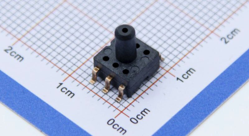
Scenario: a pressure sensor shows a zero offset, gain/sensitivity error and nonlinearity.
1) Hardware compensation scheme
Zero offset: add an op-amp stage at the sensor output and adjust a potentiometer to provide a counter bias voltage so the zero point is corrected.
Gain / temperature drift: include a thermistor in the amplifier feedback network. As temperature rises and sensor sensitivity falls, the circuit automatically increases gain to compensate.
Nonlinearity: design an analogue network (diodes/transistors) whose nonlinear response cancels the sensor’s nonlinearity; when combined, the total output becomes approximately linear.
Result: the sensor’s signal pin outputs a corrected analogue voltage. The MCU can read that directly with little or no further correction.
2) Software compensation scheme
Step 1 — Data collection & modelling
On the production line place the sensor in a thermal chamber and record raw digital outputs (ADC values) at multiple known pressures and temperatures. You’ll collect tuples like: (true_pressure, temperature, ADC_raw).
Step 2 — Build the mathematical model
Using fitting tools you might find the residual error is well described by a bivariate quadratic, for example:Pressure_compensated = a*(ADC_raw)^2 + b*(ADC_raw) + c*(temperature) + d
Use a fitting algorithm to find the optimal coefficients a, b, c, d.
Step 3 — Implement in firmware
Store the coefficients (a, b, c, d) in MCU non-volatile memory (Flash). At runtime the MCU:
reads the current
ADC_raw;reads temperature;
plugs those values into the formula;
outputs
Pressure_compensated— the high-accuracy pressure value.
Result: although the MCU reads a raw, imperfect digital value from the sensor, the onboard algorithm returns a finely compensated pressure reading.
Conclusion
Complementary relationship: In modern high-performance sensors hardware and software compensation are usually used together. Hardware takes care of the basic, common and fast errors (e.g. coarse temperature drift and zero offset) to stabilise the signal early on; software then performs the fine tuning — handling residual nonlinearity and complex cross-sensitivities to reach very high accuracy.
The above introduction only scratches the surface of the applications of pressure sensor technology. We will continue to explore the different types of sensor elements used in various products, how they work, and their advantages and disadvantages. If you’d like more detail on what’s discussed here, you can check out the related content later in this guide. If you are pressed for time, you can also click here to download the details of this guides air pressure sensor product PDF data.
For more information on other sensor technologies, please visit our sensors page.