In general, before digital processing, датчыкі ціску often describe features such as гістэрэз (pressure, temperature), linearity, temperature coefficient, and other characteristic parameters in the product specifications. However, after digital processing, pressure sensors or transmitters typically no longer describe these parameter indicators when detailing output signal characteristics; instead, they provide overall measurement accuracy parameters. This difference is not because digital processing can eliminate characteristics like hysteresis, but because after digital processing it becomes difficult to distinguish whether certain characteristics such as hysteresis are caused by the sensor element’s measurement signal or by the firmware processing itself. Therefore, it is generally more reasonable to combine the measurement errors caused by гістэрэз, temperature characteristics, and the quantization process into the final measurement accuracy, error, and long-term stability specifications of the product.
Каталог
Sensor Errors
As long as there is measurement, there will inevitably be errors. For specific applications, even if errors exist, they are relative in a certain sense. As long as the error is within an acceptable range, it can be tolerated, and professional users generally follow the principle of “sufficiency, then preference” when selecting sensors. In pressure sensor applications, the characteristics of concern include, but are not limited to, the following:
- Pressure Measurement Range: FSO-kPa (differential pressure/static pressure, gauge pressure/sealed gauge pressure, absolute pressure)
· Pressure Measurement Error: ±kPa
· Measurement Resolution: kPa/bit
· Operating Voltage/Current
· Storage and Operating Temperature Range, measurement medium
· Pressure Response Characteristics, паўтаральнасць, доўгатэрміновая стабільнасць

Beneath these pressure parameters lie the sensor’s core or module that can convert pressure into an electrical signal. There are multiple principles for measuring pressure, but not every principle can cover all types and ranges of pressure. These principles include:
- П'езарэзістыўныя
- Sputtered Thin Film
- Silicon Resonant
- Ёмісты
- Eddy Current
- Force Balance, Melted Quartz Bourdon Tube
- Strain Gauge …
Below is a brief error analysis for pressure sensors based on the piezoresistive principle.
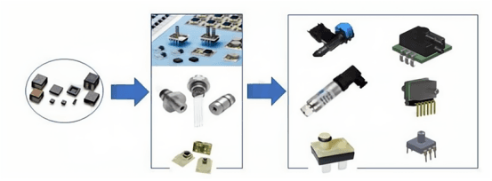
Figure-1: From silicon chip каб various packaging applications of piezoresistive pressure sensors
In Figure-1, several typical forms are listed that are widely used in various fields based on piezoresistive pressure sensors from bare dies to several types of packaging. Some product types only have external packaging; some have analog signal outputs within the corresponding range that are temperature compensated and calibrated for interchangeability; some further amplify the analog signal; and others perform digital processing before outputting. There are also pressure transmitters that, after digital calibration, use corresponding interface protocols that are widely applied in industry, as well as integrated modules that include other sensors such as temperature or gas sensors for automotive, medical, and other industries. Additionally, some devices use the pressure characteristics of the medium being measured to determine other physical quantities—for example, flow sensors based on low differential pressure sensors used in ventilators.
Generally speaking, before digital processing, датчыкі ціску often describe features such as гістэрэз (pressure, temperature), linearity, and temperature coefficient in their specification sections. After digital processing, however, pressure sensors or transmitters typically do not describe these indicators when detailing the output signal characteristics, but instead provide overall measurement accuracy parameters. This difference is not because digital processing can eliminate characteristics like гістэрэз, but because it becomes difficult after digital processing to distinguish whether the characteristics (e.g., hysteresis) are caused by the sensor element’s measurement signal or by the firmware processing itself. Therefore, the measurement errors caused by гістэрэз and temperature characteristics, along with quantization errors, are generally combined into the final product specifications for measurement accuracy, error, and long-term stability.
Digital conditioning often seldom addresses the symmetry of the sensor bridge. If one considers the effect of the offset distribution at the zero-load point of a piezoresistive pressure sensor on the gain of the front-end amplification circuit, as well as the impact of the subsequent ADC on the effective signal (FSO) resolution due to gain variations, a comprehensive approach is required. After digital processing, unless necessary, the offset is calculated from the specified zero point.
Analog compensation and calibration, before the ADC participates in processing, can significantly enhance product interchangeability by improving symmetry (0-point offset output approaching 0V), temperature sensitivity, and output consistency. Therefore, both methods have their characteristics. In the subsequent error analysis of pressure sensors, only pressure products that have undergone temperature compensation and calibration using resistor networks will be discussed, rather than those after digital processing.
Based on the characteristics of piezoresistive pressure sensors, the error treatment is generally divided into two types:
- Compensable Errors (generally caused by temperature effects and are repeatable)
- Non-compensable Errors (generally caused by pressure, temperature, and packaging stress, and are non-repeatable)
Of course, even for the compensable portion of the error, different compensation methods can achieve varying degrees of error cancellation.
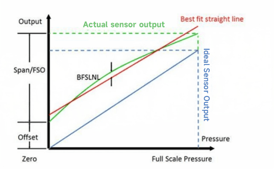
Figure-2: Comparison of the output characteristics (green) of a piezoresistive pressure sensor at a fixed temperature with the ideal pressure sensor output (blue)
For the subsequent error analysis, Figure-2 shows the general output characteristics of a piezoresistive pressure sensor. The terms used in the figure are as follows:
- Zero: Ideal reference zero point
- Offset: Actual zero-load output deviation, i.e., the output voltage when zero load is applied
- FSO: Full Scale Output, the difference in output signal from the full scale pressure to the zero point
- BFSLNL: Non-Linearity relative to the Best Fit Straight Line
Sensor Characteristics and Error Analysis
Next, we take a detailed look at a medium-pressure 40kPa piezoresistive pressure sensor from WF brand. After packaging, calibration, and Кампенсацыя тэмпературы using a 316L stainless steel pressure module, the parameters are as follows:

The data in the table (e.g. ±1% FS, etc.) is usually the final accuracy obtained “after calibration/compensation”, which has already corrected for most repeatable temperature errors, gain errors, zero bias, etc. The true “uncalibrated” deviation often takes into account various types of scatter including initial zero point, sensitivity, package stress, etc., which can easily add up to more than ±10% FS.
The true “uncalibrated” deviation often takes into account various types of scatter, including initial zero, sensitivity, package stress, etc., which can easily add up to more than ±10% FS.
Therefore, many manufacturers only list the calibrated or compensated combined accuracy (e.g., 1% FS, 2% FS) in their “final specifications” and do not directly indicate in the final product data sheet how much ±% FS error the “original die” may have.
Error Influencing Factors
Typical error influences include reference voltage errors, amplifier errors, sensor errors, and the effect of noise on measurement accuracy.
(1) Reference voltage error
The reference voltage is used to compare with the actual measurement value, so the actual value of this reference voltage is very important, and periodic calibration or software calibration of the reference voltage is required to correct this basic measurement error. A temperature coefficient of 100 ppm/°C at 0°C to 25°C will have an error of up to 2500 ppm, or 0.25% of the full scale range.
(2) Amplifier Error
Operational amplifiers can introduce errors due to their out-of-phase zero drift and other reasons. Sensor signal input operational amplifier that will affect the measurement accuracy. Such as pressure sensors, pressure sensors, for example, a 20mV full-scale signal will have a 5% offset, that is, 1mV input bias voltage. This input bias error can directly reduce the measurement accuracy, with sufficient dynamic range of the A/D converter is possible to use software to eliminate this error.
(3) Sensor Error
Sensors are unlikely to reach an ideal state because of processing, and errors can occur. It may be difficult to correct sensor errors. For example, in the case of pressure sensors, even if they are linearly calibrated during the manufacturing process, the amount of variation in the output scale factor between different devices in the application is still high. The reference voltage of the pressure sensor is usually generated by the excitation, which produces a proportional measurement method through a Whiston bridge, which eliminates the drift error to some extent, but there will still be a bias voltage generated because the bridge cannot be completely symmetrical to each other. Taking the pressure sensor as an example, the offset of 1 low pressure sensor, its bias error is largely caused by the bridge asymmetry.
(4) Noise effects
Noise has many sources, including coupled noise from nearby high-speed digital logic circuits, power supplies, fan motors, solenoid valves, and RF EMI. Noise can be reduced by proper grounding design, shielding methods and board layout. In addition, operational amplifiers can be selected that minimize introduced noise and have sufficient gain bandwidth. Operational amplifiers can be evaluated on the basis of the amount of introduced noise, which is determined from measurements of signals over an unrestricted bandwidth (wide bandwidth) or a defined bandwidth.
A/D Converters
When using an A/D converter, background noise is a determining factor in the available measurement accuracy. When a device is rated for 24-bit resolution, the actual accuracy achieved by the converter is usually lower due to limitations caused by noise. A distinction needs to be made here between the effective bit and the very low noise value, where the effective bit specification is calculated from the noise level RMS value, and the very low noise value is based on the peak-to-peak value, which typically corresponds to as much as 6.6 times the statistical RMS value. Therefore, the very low noise specification indicates the effective resolution of the converter, which remains stable at LSB bits above the background noise. Special attention also needs to be paid to the limitations in the specification, such as the reference voltage and input range, which may vary from application to application, and the datasheet promises may differ considerably from the actual ratio.
Operational Amplifiers
It is difficult for an amplifier to achieve low noise and high gain at the same time. It is then necessary to bring the noise level of the amplifier into the same range as its error. All semiconductor amplifiers have 1/f noise, also known as flicker noise, which is a fundamental phenomenon due to the material. Contrary to frequency, below a specific noise inflection point, the noise density increases exponentially and becomes very large at low frequencies. Few amplifiers can realize this combination of low noise and high gain characteristics in a single chip at low cost.
To achieve low noise and high gain, hybrid multi-amplifier circuits can be designed, using a combination of input amplifiers with a high input impedance, input error correction circuitry, and a second (or third) compensation amplifier to achieve the desired gain. Amplifiers that concentrate on one parameter often present serious problems in other areas.
Апошнія думкі
This is why, in practical applications, if we directly purchase an uncalibrated bare-die або simply packaged piezoresistive pressure sensor and handle the circuit design and temperature compensation ourselves, we may face a significant initial offset. However, if we buy a digitally compensated/calibrated pressure sensor or transmitter with built-in compensation, we can directly achieve the smaller overall error (such as ±1% FS) indicated in the datasheet.
Прыведзенае вышэй увядзенне толькі драпае паверхню прымянення тэхналогіі датчыка ціску. Мы працягнем вывучаць розныя тыпы сэнсарных элементаў, якія выкарыстоўваюцца ў розных прадуктах, як яны працуюць, а таксама іх перавагі і недахопы. Калі вы жадаеце атрымаць больш падрабязную інфармацыю аб тым, што тут абмяркоўваецца, вы можаце праверыць адпаведнае змесціва далей у гэтым кіраўніцтве. Калі ў вас няма часу, вы таксама можаце націснуць тут, каб загрузіць падрабязную інфармацыю аб гэтым даведніку Датчыкі датчыка ціску паветра PDF дадзеныя.
Для атрымання дадатковай інфармацыі аб іншых сэнсарных тэхналогіях, калі ласка Наведайце старонку датчыкаў.